R

M

N

P

Q

(See Note 2)

V

T

VS Electrical S

Service

D*

V

V

V

= VENT TERMINAL

X = AIR SUPPLY INLET

= AREA WHERE TERMINAL IS NOT PERMITTED

A

=

12 inches

clearances above grade, veranda,

L**

=

.7 ft

clearance above paved


(See Note 1)

porch, deck or balcony


(See Note 1)


sidewalk or a paved driveway

B

=

12 inches

clearances to window or door


located on public property

M*** =

18 inches

clearance under veranda, porch,


that may be opened, or to perma-


nently closed window. (Glass)


deck, balcony or overhang

D*

=

18 inches

vertical clearance to unventilated


42 inches

vinyl soffit and overhang


soffit or to ventilated soffit located

S

=


6 inches

clearance from sides of electri-


above the terminal


(See Note 5)


cal service


*30 inches

for vinyl clad soffits and below

T

=

12 inches

clearance above electrical


electrical service


(See Note 5)


service


F

=

9 inches

clearance to outside corner


Alcove Applications


G

=

6 inches

clearance to inside corner


N


=

6 inches

non-vinyl sidewalls


H

=

3 ft. (Canada)

not to be installed above a gas


12 inches

vinyl sidewalls


meter/regulator assembly within 3


P


=

8 ft.


feet (90 cm) horizontally from the


center-line of the regulator


QMIN


RMAX


I

=

3 ft

clearance to gas service regulator


1 cap


3 feet


2 x Q ACTUAL


vent outlet


J

=

9 inches (U.S.A.)


2 caps


6 feet


1 x Q ACTUAL


12 inches (Canada) clearance to non-mechanical


3 caps


9 feet


2/3 x Q ACTUAL


air supply inlet to building or the


combustion air inlet to any other


4 caps


12 feet


1/2 x Q ACTUAL


appliance


K

=

3 ft. (U.S.A.)


QMIN

= # termination caps x 3

RMAX = (2 / # termination caps) x QACTUAL


6 ft. (Canada)

clearance to a mechanical (pow-


ered) air supply inlet


**a vent shall not terminate directly above a sidewalk or paved driveway which is located between two single family dwellings and serves both dwellings.

***only permitted if veranda, porch, deck or balcony is fully open on a minimum of 2 sides beneath the floor, or meets Note 2.

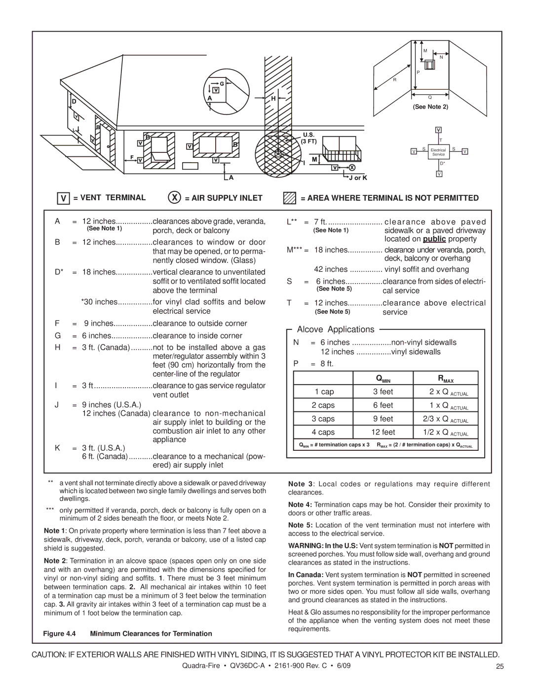
Note 1: On private property where termination is less than 7 feet above a sidewalk, driveway, deck, porch, veranda or balcony, use of a listed cap shield is suggested.

Note 2: Termination in an alcove space (spaces open only on one side and with an overhang) are permitted with the dimensions specified for

vinyl or non-vinyl siding and soffits. 1. There must be 3 feet minimum between termination caps. 2. All mechanical air intakes within 10 feet of a termination cap must be a minimum of 3 feet below the termination cap. 3. All gravity air intakes within 3 feet of a termination cap must be a minimum of 1 foot below the termination cap.

Figure 4.4 Minimum Clearances for Termination

Note 3: Local codes or regulations may require different clearances.

Note 4: Termination caps may be hot. Consider their proximity to doors or other traffic areas.

Note 5: Location of the vent termination must not interfere with access to the electrical service.

WARNING: In the U.S: Vent system termination is NOT permitted in screened porches. You must follow side wall, overhang and ground clearances as stated in the instructions.

In Canada: Vent system termination is NOT permitted in screened porches. Vent system termination is permitted in porch areas with two or more sides open. You must follow all side walls, overhang and ground clearances as stated in the instructions.

Heat & Glo assumes no responsibility for the improper performance of the appliance when the venting system does not meet these requirements.

CAUTION: IF EXTERIOR WALLS ARE FINISHED WITH VINYL SIDING, IT IS SUGGESTED THAT A VINYL PROTECTOR KIT BE INSTALLED.

Quadra-FireQV36DC-A2161-900 Rev. C • 6/09

25

Page 22
Image 22
Quadra-Fire QV36DC-A owner manual Alcove Applications

QV36DC-A specifications

The Quadra-Fire QV36DC-A is a remarkable addition to the world of home heating, exemplifying innovation and efficiency in gas-burning fireplace inserts. Designed for those who seek both aesthetics and functionality in their living spaces, this model offers an impressive blend of features and technologies that enhance not only warmth but also the overall ambiance of any room.

One of the standout characteristics of the QV36DC-A is its direct vent design. This technology allows for a safe and efficient venting system that draws outside air for combustion, ensuring that indoor air quality is maintained. This feature eliminates the need for a traditional chimney, making it an ideal choice for modern homes or those with limited space. The direct vent capability also contributes to a higher efficiency rating, making it more cost-effective and environmentally friendly.

Another key feature of this model is its large viewing area, which is framed by a sleek and stylish surround. The expansive glass front provides a stunning visual display of the flames, creating a warm and inviting atmosphere. The QV36DC-A also comes with a range of decorative options, including various finish choices and customizable log sets, allowing homeowners to tailor the look of their fireplace to suit their personal style.

The QV36DC-A is equipped with advanced heating technologies, including a powerful heating capacity of up to 30,000 BTUs. This ensures that it can effectively heat larger spaces while maintaining a comfortable environment. The unit features adjustable fan speeds and a variable flame control system, allowing users to manipulate the level of heat and ambiance according to their preferences.

Additionally, the Quadra-Fire QV36DC-A is designed for ease of use and maintenance. The included remote control makes it convenient to adjust settings from a distance, while the self-cleaning glass door reduces the frequency of maintenance chores. The durable construction and high-quality materials ensure longevity, making it a wise investment for homeowners.

With its blend of functionality, efficiency, and beauty, the Quadra-Fire QV36DC-A stands as a premier choice for anyone looking to enhance their living space with the warmth and comfort of a gas fireplace insert. Its thoughtful design and advanced features make it not just a source of heat, but a centerpiece that elevates the overall ambiance of any home.