FishFinder L470
Instruction Manual
Raymarine
Installation
Contents
Introduction
Operating Instructions
4 Setup Instructions
Specifications
Maintenance and Troubleshooting
Page
List of Figures
Frequency Menu Item
viii
Introduction
1 - Introduction
About the FishFinder L470
System Components
Optional Accessories
Standard Equipment
Standard Transducers
Transducer switch box select between two L470
About the Transducer
2 - Installation
Installation
Use a transom-mount transducer if
Selecting the Correct Type of Transducer
Use a thru-hull transducer if
Use an in-hull transducer if
Positioning the Transom-Mount Transducer
Assembling the Transducer Bracket
Use a trolling motor transducer if
Use a Sidelooker transducer
Transducer Bracket Side View
Transducer Mounted on Transom
Allow a clearance of at least 10 inches 254 mm 10 254 mm
Transducer in released position
Mounting the Transducer
No!No!No
Correct Mounting Position
Mounting the Transom-Mount Transducer
3. Remove the two screws and the bracket covering the paddle wheels
Installation Notes - Thru-Hull Transducer
Installation Notes - In-Hull Transducer
Installation Notes - Trolling Motor Transducers
Installation Notes - Transducer for Speed and Temperature Only
EMC Installation Guidelines
Suppression Ferrites
Dismounting the Display Unit
Mounting the Display Unit - Standard Mount
2-25/32
Dimensions
70 mm
210 mm
Flush-mount Installation
Mounting the Display Unit - Flush Mount
Disassembling from Bracket
Installing the Transducer Cable
Fiberglass 1/4 6mm Aluminum 1/2 13 mm
Installing Cable on Transom
Cable feed-thru cap Cable clamp 1 25 mm Hull projections
Installation with Separate Speed and Temperature Sensors
Installing the Transducer Cable - Sidelooker Option
Installing the Transducer Cable
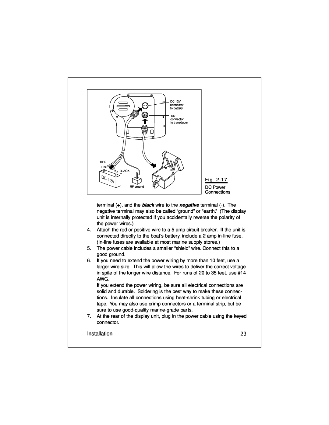
Making the DC Power Connections
RF ground
DC Power Connections
DC 12V connector to battery T/D connector to transducer RED BLACK
Calibrating the Sensors
higher value for Speed Cal. If the display unit is reading high, use a smaller number for Speed Cal. You may enter any value between 75 and
Operating Instructions
3 - Operating Instructions
Controls on Display Panel
CLEAR
Up and down arrows - and
Left and right arrows - and
Setup Memory
Turning the Power On and Off
Lamp/Contrast Menu
Mode
Operating Pages
Function
See page
is turned on
Only if Sidelooker feature
Auto frequency on Transducer frequency
FishFinder Page
Shallow alarm set
Top of display
Fish alarm set
This entry shows the speed of the boat through the water
Center of display
From the System Setup Menu, you can turn this item off or
Bottom of display
Choosing a Frequency
When the boat is moving very fast
Fish Indications
50 kHz 200 kHz
An arch-shaped image indicates a fish
Bottom Indications
Rocks
Bottom Conditions
Hard Sand Soft Mud
WindowContents
Window Page
Options for Window Page
Option A Option C Option E Option G
Option B Option D Option F Option H
Sidelooker Page
Once the Sidelooker feature has been turned on, you can reach the Sidelooker page easily. Press the or buttons on the Page Control Pad until the Sidelooker Page appears. The unit will present a display similar to Fig
Here are the special items on this display
Bottom/Shore
Digital Page
button. The Log may be reset to zero from the
A-Scope Mode
Zoom Mode
Bottom Lock Mode
Performance Modes
Zoom display
Performance Modes
Zoom Mode
Zoom magnification
A-Scope Bottom Coverage Mode
Bottom coverage
Bottom Lock Mode
the selected range, then Bottom Lock will not display the bottom image
The Setup Menu
4 - Setup Instructions
Setup Instructions
Fig.4-1
Sidelooker
Range Setting
Setup Instructions
Sensitivity Setting
Auto sensitivity
Changing the Chart Speed Setting
Chart Speed Setting
Frequency Setting
AUTO frequency
Resetting the Log
Fig.4-8
System Setup Menu
The unit can present the display information in one of seven
different languages. English is the default language which
Setup Instructions
For example, if the temperature reading on
Shallow Alarm
CLEAR
water. You can silence the buzzer again by pressing the
conditions occurs shallow, deep, or fish alarm. For the
Units used for speedUnits used by
Code
Zoom Select Menu
Setup Menus for Zoom Mode
feature is particularly useful when fishing for species of fish
button to leave this display, and store the Auto Zoom setting
Zoom Screen Split/Full Menu Item
Bottom Lock Range Menu Item
Setup Menus for Bottom Lock Mode
Bottom Lock Split/Full Menu Item
Setup Menu for Window Page
Setup Instructions for Sidelooker
Resetting from the Digital Page
Sidelooker Range Menu Item
Sidelooker Sensitivity Menu Item
Sidelooker Chart Speed Menu Item
Display Option Information Shown
Sidelooker View Menu Item
Combining Displays
Resetting the Unit to Factory Defaults
Default - US model Default - Europe model
Default Settings
Cleaning Instructions
5 - Maintenance and Troubleshooting
Troubleshooting Suggestions
Maintenance and Troubleshooting
The display unit “freezes” temporarily or permanently
The FishFinder does not display fish arches
The display unit does not see the bottom or fish
The display unit shows lots of background “noise”
The depth setting flashes often
For marine product and services information
How to Contact Raymarine
For accessories and parts
Servicing a Thru-Hull Transducer
For technical support
For product repair service
Raymarine in Europe
Prepaid Return Service
Maintenance and Troubleshooting
General Information
6 - Specifications
Specifications
Feet, fathoms, meters
FishFinder Functions
Connectors
Connector Diagrams
Glossary
Glossary of Terms
Statute mile 5280 ft
Nautical mile 6076 feet
Warranty Limitations
Limited Warranty Certificate