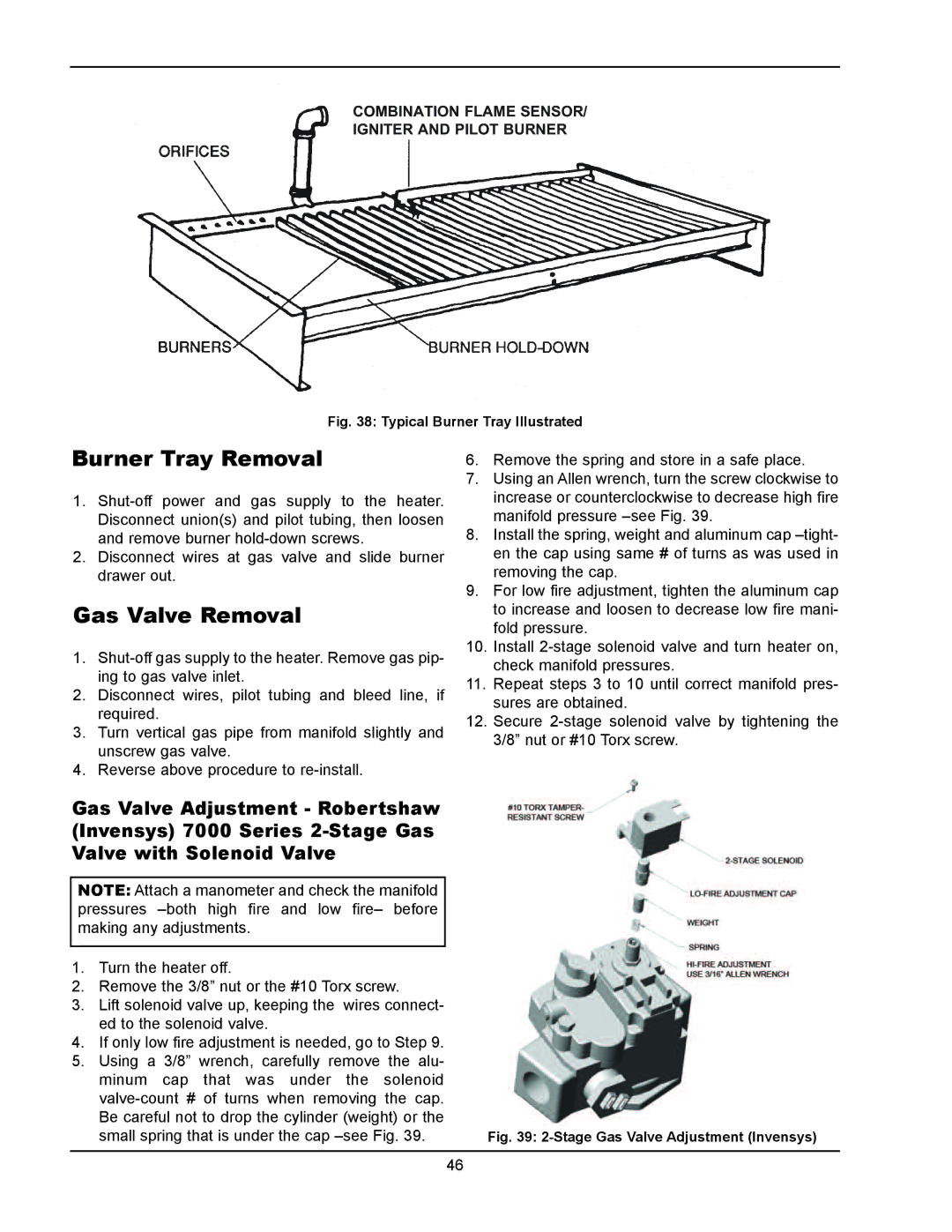
COMBINATION FLAME SENSOR/ IGNITER AND PILOT BURNER
Fig. 38: Typical Burner Tray Illustrated
burner Tray Removal
1.
2.Disconnect wires at gas valve and slide burner drawer out.
Gas Valve Removal
1.
2.Disconnect wires, pilot tubing and bleed line, if required.
3.Turn vertical gas pipe from manifold slightly and unscrew gas valve.
4.Reverse above procedure to
Gas Valve Adjustment - Robertshaw (Invensys) 7000 Series
NOTE: Attach a manometer and check the manifold pressures
1.Turn the heater off.
2.Remove the 3/8” nut or the #10 Torx screw.
3.Lift solenoid valve up, keeping the wires connect- ed to the solenoid valve.
4.If only low fire adjustment is needed, go to Step 9.
5.Using a 3/8” wrench, carefully remove the alu- minum cap that was under the solenoid
6.Remove the spring and store in a safe place.
7.Using an Allen wrench, turn the screw clockwise to increase or counterclockwise to decrease high fire manifold pressure
8.Install the spring, weight and aluminum cap
9.For low fire adjustment, tighten the aluminum cap to increase and loosen to decrease low fire mani- fold pressure.
10.Install
11.Repeat steps 3 to 10 until correct manifold pres- sures are obtained.
12.Secure
Fig. 39: 2-Stage Gas Valve Adjustment (Invensys)
46