Controls—General
Relief Valve
A new combination temperature and pressure (T&P) relief valve, complying with the Standard for Relief Valves and Automatic Gas
The pressure rating of the relief valve must not exceed the 160 maximum working pressure indicated on the water heater rating plate. The BTUH rating of the relief valve must not be less than the BTUH input of the heater.
Connect the outlet of the relief valve to a suitable open drain. The discharge line must pitch downward from the valve to allow complete draining (by gravity) of the relief valve and discharge line. The discharge line should be no smaller than the outlet of the valve. The end of the discharge line should not be threaded or concealed, and should be protected from freezing. No valve of any type, restriction or reducer coupling, should be installed in the discharge line. Local codes shall govern installation of the relief valve.
Pump Time Delay
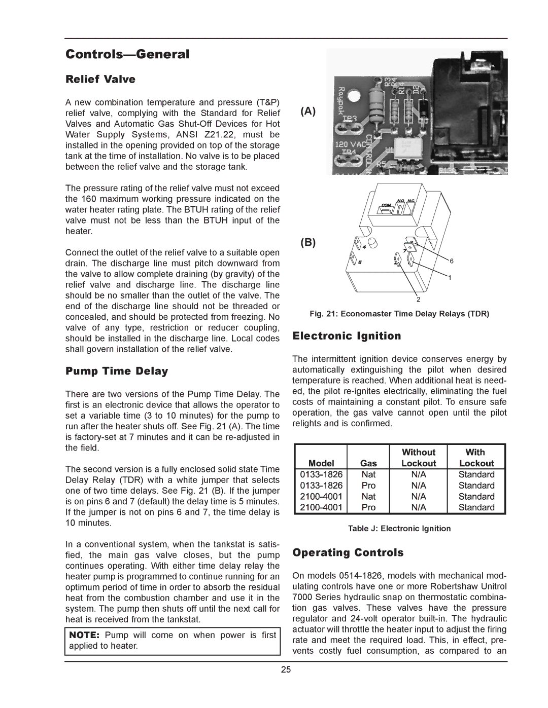
There are two versions of the Pump Time Delay. The first is an electronic device that allows the operator to set a variable time (3 to 10 minutes) for the pump to run after the heater shuts off. See Fig. 21 (A). The time is
The second version is a fully enclosed solid state Time Delay Relay (TDR) with a white jumper that selects one of two time delays. See Fig. 21 (B). If the jumper is on pins 6 and 7 (default) the delay time is 5 minutes. If the jumper is not on pins 6 and 7, the time delay is 10 minutes.
In a conventional system, when the tankstat is satis- fied, the main gas valve closes, but the pump continues operating. With either time delay relay the heater pump is programmed to continue running for an optimum period of time in order to absorb the residual heat from the combustion chamber and use it in the system. The pump then shuts off until the next call for heat is received from the tankstat.
NOTE: Pump will come on when power is first applied to heater.
(A)
(B)
6
1
2
Fig. 21: Economaster Time Delay Relays (TDR)
Electronic Ignition
The intermittent ignition device conserves energy by automatically extinguishing the pilot when desired temperature is reached. When additional heat is need- ed, the pilot
Table J: Electronic Ignition
Operating Controls
On models
25