SECTION C: Installation

Model

Manifold Gas Pressure

(High Fire Values)

No.


Natural Gas

Propane Gas


503

-0.1

-0.1


753

-0.1

-0.1


1003

-0.2

-0.2


1253

-0.1

-0.1


1503

-0.4

-0.3


1753

0.4

0.4


2003

0.6

0.6


NOTE: Manifold pressures should be + 0.2” WC.

Table I: Manifold Gas Pressure Settings

During normal operation, carbon dioxide should be 8.0 to 9.0% at full fire for natural gas and between 9.0 and 10.0% for propane gas. Carbon monoxide should be ‹100ppm.

Electrical Power Connections

Installations must follow these codes:

National Electrical Code and any other national, state, provincial or local codes or regulations hav- ing jurisdiction.

Safety wiring must be NEC Class 1.

Heater must be electrically grounded as required by the NEC.

In Canada, CSA C22. 1 C.E.C. Part 1.

The MVB 503-1503 heaters are wired for 120 VAC, 12 amps while the MVB 1753 & 2003 heaters are wired for 120 VAC, 18 amps. Consult the wiring diagram shipped with the heater. Before starting the heater, check to ensure proper voltage to the heater and pump.

Boiler mounted pumps (up to ¾ hp) get their power supply directly from the boiler power supply (connec- tions in rear wiring box). Install a circuit breaker sized sufficiently for both the heater and the pump. Pumps larger than ¾ hp must use a separate power supply and run the power through the optional pump contactor which is located in the rear wiring box (see Fig. 16). Use appropriately-sized wire as defined by NEC, CSA and/or local codes. All primary wiring should be 125% of minimum rating.

If any of the original wire as supplied with the heater must be replaced, it must be replaced with 105°C wire or its equivalent.

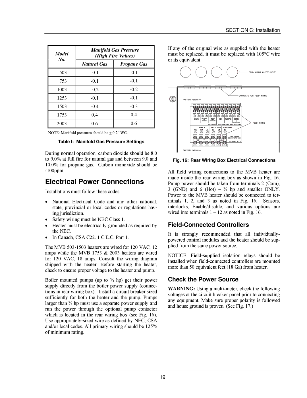
Fig. 16: Rear Wiring Box Electrical Connections

All field wiring connections to the MVB heater are made inside the rear wiring box as shown in Fig. 16. Pump power should be taken from terminals 2 (Com), 3 (GND) and 6 (Hot) – ¾ hp and smaller ONLY. Power to the MVB heater should be connected to ter- minals 1, 2, and 3 as noted in Fig. 16. Sensors, interlocks, Enable/disable, and various options are wired into terminals 1 – 12 as noted in Fig. 16.

Field-Connected Controllers

It is strongly recommended that all individually- powered control modules and the heater should be sup- plied from the same power source.

NOTICE: Field-supplied isolation relays should be installed when field-connected controllers are mounted more than 50 equivalent feet (18 Ga) from heater.

Check the Power Source

WARNING: Using a multi-meter, check the following voltages at the circuit breaker panel prior to connecting any equipment. Make sure proper polarity is followed and house ground is proven. (See Fig. 17.)

19

Page 21
Image 21
Raypak 503-2003 manual Electrical Power Connections, Field-Connected Controllers, Check the Power Source

503-2003 specifications

The Raypak 503-2003 is a notable entry in the world of water heating solutions, renowned for its efficiency and reliability in both residential and commercial settings. This model is designed to provide exceptional performance while maintaining ease of use and minimization of environmental impact.

One of the standout features of the Raypak 503-2003 is its advanced heating technology. The unit utilizes a durable, copper heat exchanger which ensures quick and efficient heating of water. This heat exchanger is known for its ability to transfer heat effectively, leading to reduced energy consumption and lower utility bills. The design also allows for a seamless operation, ensuring that the system heats water swiftly without sacrificing performance.

In addition to its efficient heating capabilities, the Raypak 503-2003 is equipped with innovative controls. The digital control panel allows users to easily set and adjust the desired water temperature. This feature provides a level of convenience that simplifies operation while enhancing user experience. Furthermore, the smart technology employed in the unit ensures that it operates within optimal parameters, avoiding unnecessary energy expenditure.

Durability is another hallmark of the Raypak 503-2003. Built with heavy-duty components, this water heating solution is designed to withstand the rigors of continuous use. The rugged construction ensures longevity, making it a cost-effective investment for homeowners and businesses alike. Moreover, the unit is designed to be resistant to corrosion and wear, further extending its lifespan and reliability.

The energy efficiency of the Raypak 503-2003 is a crucial characteristic that sets it apart from competitors. Rated with a high efficiency score, this model contributes to lower emissions and is environmentally friendly. It adheres to various energy standards, making it a suitable choice for those looking to reduce their carbon footprint while enjoying reliable water heating.

Noise reduction is another important feature of the Raypak 503-2003. Designed with quiet operation in mind, the unit operates with minimal noise pollution, allowing for a pleasant environment in both residential and commercial spaces.

In summary, the Raypak 503-2003 combines advanced heating technology, user-friendly controls, durability, and energy efficiency into a robust water heating system. This makes it an excellent choice for those in need of dependable and sustainable heating solutions. Whether for daily home use or for larger commercial applications, the Raypak 503-2003 stands out as a leader in its class.