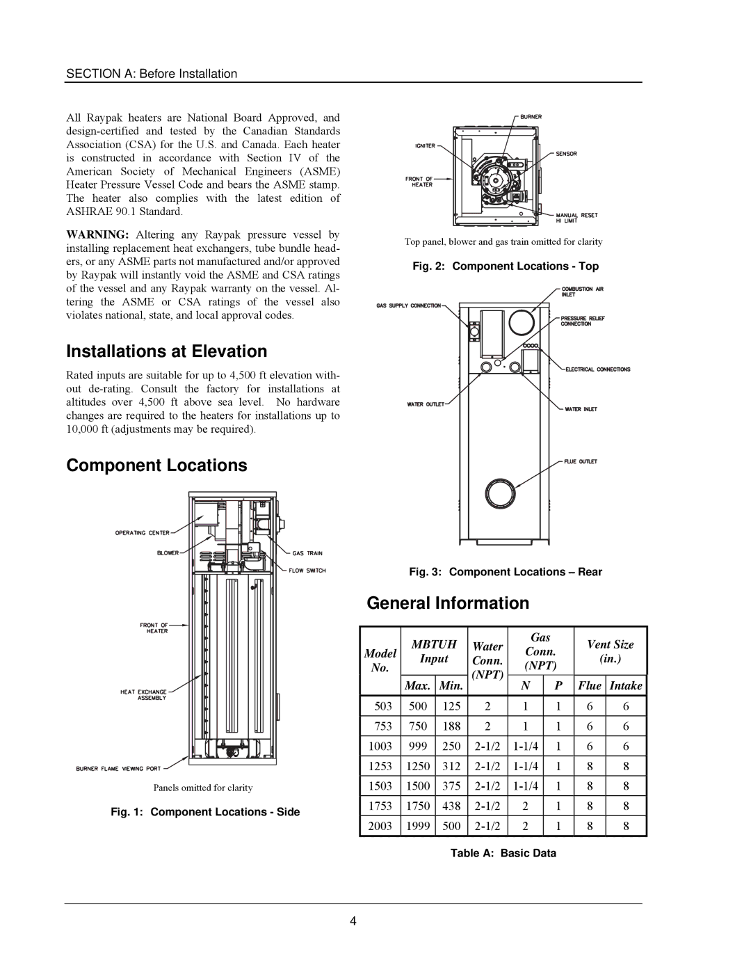
503-2003 specifications
The Raypak 503-2003 is a notable entry in the world of water heating solutions, renowned for its efficiency and reliability in both residential and commercial settings. This model is designed to provide exceptional performance while maintaining ease of use and minimization of environmental impact.One of the standout features of the Raypak 503-2003 is its advanced heating technology. The unit utilizes a durable, copper heat exchanger which ensures quick and efficient heating of water. This heat exchanger is known for its ability to transfer heat effectively, leading to reduced energy consumption and lower utility bills. The design also allows for a seamless operation, ensuring that the system heats water swiftly without sacrificing performance.
In addition to its efficient heating capabilities, the Raypak 503-2003 is equipped with innovative controls. The digital control panel allows users to easily set and adjust the desired water temperature. This feature provides a level of convenience that simplifies operation while enhancing user experience. Furthermore, the smart technology employed in the unit ensures that it operates within optimal parameters, avoiding unnecessary energy expenditure.
Durability is another hallmark of the Raypak 503-2003. Built with heavy-duty components, this water heating solution is designed to withstand the rigors of continuous use. The rugged construction ensures longevity, making it a cost-effective investment for homeowners and businesses alike. Moreover, the unit is designed to be resistant to corrosion and wear, further extending its lifespan and reliability.
The energy efficiency of the Raypak 503-2003 is a crucial characteristic that sets it apart from competitors. Rated with a high efficiency score, this model contributes to lower emissions and is environmentally friendly. It adheres to various energy standards, making it a suitable choice for those looking to reduce their carbon footprint while enjoying reliable water heating.
Noise reduction is another important feature of the Raypak 503-2003. Designed with quiet operation in mind, the unit operates with minimal noise pollution, allowing for a pleasant environment in both residential and commercial spaces.
In summary, the Raypak 503-2003 combines advanced heating technology, user-friendly controls, durability, and energy efficiency into a robust water heating system. This makes it an excellent choice for those in need of dependable and sustainable heating solutions. Whether for daily home use or for larger commercial applications, the Raypak 503-2003 stands out as a leader in its class.

