SECTION C: Installation

3.The vent must be insulated through the length of the horizontal run.

Termination

The flue direct vent cap MUST be mounted on the ex- terior of the building. The direct vent cap cannot be installed in a well or below grade. The direct vent cap must be installed at least 1 ft above ground level and above normal snow levels. The Raypak-approved stainless steel flue direct vent cap must be used (sales order option D-15). The vent terminal must be located NO CLOSER than 12” off the wall.

WARNING: No substitutions of flue pipe or vent cap material are allowed. Such substitutions would jeopard- ize the safety and health of inhabitants.

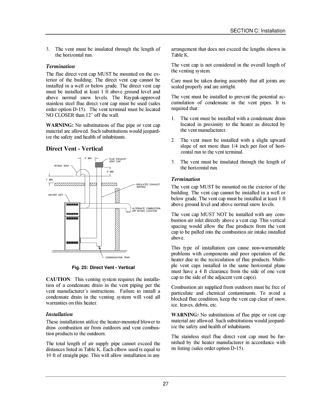
Direct Vent - Vertical

Fig. 25: Direct Vent - Vertical

CAUTION: This venting system requires the installa- tion of a condensate drain in the vent piping per the vent manufacturer’s instructions. Failure to install a condensate drain in the venting system will void all warranties on this heater.

Installation

These installations utilize the heater-mounted blower to draw combustion air from outdoors and vent combus- tion products to the outdoors.

The total length of air supply pipe cannot exceed the distances listed in Table K. Each elbow used is equal to 10 ft of straight pipe. This will allow installation in any

arrangement that does not exceed the lengths shown in Table K.

The vent cap is not considered in the overall length of the venting system.

Care must be taken during assembly that all joints are sealed properly and are airtight.

The vent must be installed to prevent the potential ac- cumulation of condensate in the vent pipes. It is required that:

1.The vent must be installed with a condensate drain located in proximity to the heater as directed by the vent manufacturer.

2.The vent must be installed with a slight upward slope of not more than 1/4 inch per foot of hori- zontal run to the vent terminal.

3.The vent must be insulated through the length of the horizontal run.

Termination

The vent cap MUST be mounted on the exterior of the building. The vent cap cannot be installed in a well or below grade. The vent cap must be installed at least 1 ft above ground level and above normal snow levels.

The vent cap MUST NOT be installed with any com- bustion air inlet directly above a vent cap. This vertical spacing would allow the flue products from the vent cap to be pulled into the combustion air intake installed above.

This type of installation can cause non-warrantable problems with components and poor operation of the heater due to the recirculation of flue products. Multi- ple vent caps installed in the same horizontal plane must have a 4 ft clearance from the side of one vent cap to the side of the adjacent vent cap(s).

Combustion air supplied from outdoors must be free of particulate and chemical contaminants. To avoid a blocked flue condition, keep the vent cap clear of snow, ice, leaves, debris, etc.

WARNING: No substitutions of flue pipe or vent cap material are allowed. Such substitutions would jeopard- ize the safety and health of inhabitants.

The stainless steel flue direct vent cap must be fur- nished by the heater manufacturer in accordance with its listing (sales order option D-15).

27

Page 29
Image 29
Raypak 503-2003 manual Direct Vent Vertical

503-2003 specifications

The Raypak 503-2003 is a notable entry in the world of water heating solutions, renowned for its efficiency and reliability in both residential and commercial settings. This model is designed to provide exceptional performance while maintaining ease of use and minimization of environmental impact.

One of the standout features of the Raypak 503-2003 is its advanced heating technology. The unit utilizes a durable, copper heat exchanger which ensures quick and efficient heating of water. This heat exchanger is known for its ability to transfer heat effectively, leading to reduced energy consumption and lower utility bills. The design also allows for a seamless operation, ensuring that the system heats water swiftly without sacrificing performance.

In addition to its efficient heating capabilities, the Raypak 503-2003 is equipped with innovative controls. The digital control panel allows users to easily set and adjust the desired water temperature. This feature provides a level of convenience that simplifies operation while enhancing user experience. Furthermore, the smart technology employed in the unit ensures that it operates within optimal parameters, avoiding unnecessary energy expenditure.

Durability is another hallmark of the Raypak 503-2003. Built with heavy-duty components, this water heating solution is designed to withstand the rigors of continuous use. The rugged construction ensures longevity, making it a cost-effective investment for homeowners and businesses alike. Moreover, the unit is designed to be resistant to corrosion and wear, further extending its lifespan and reliability.

The energy efficiency of the Raypak 503-2003 is a crucial characteristic that sets it apart from competitors. Rated with a high efficiency score, this model contributes to lower emissions and is environmentally friendly. It adheres to various energy standards, making it a suitable choice for those looking to reduce their carbon footprint while enjoying reliable water heating.

Noise reduction is another important feature of the Raypak 503-2003. Designed with quiet operation in mind, the unit operates with minimal noise pollution, allowing for a pleasant environment in both residential and commercial spaces.

In summary, the Raypak 503-2003 combines advanced heating technology, user-friendly controls, durability, and energy efficiency into a robust water heating system. This makes it an excellent choice for those in need of dependable and sustainable heating solutions. Whether for daily home use or for larger commercial applications, the Raypak 503-2003 stands out as a leader in its class.