Connect to CALL monitor. Show the Switch Display.
6. AUDIO OUT (R/L)
Connect to monitor or speaker.
*IPS should be set to 25A (for NTSC) or 18A (for PAL)
7.AUDIO IN
Connect to audio source, such as microphone.
*IPS should be set to 25A (for NTSC) or 18A (for PAL)
8.MAIN
Connect to Main monitor
9. Loop
Connect video signal between Input port and Loop port to make a loop.
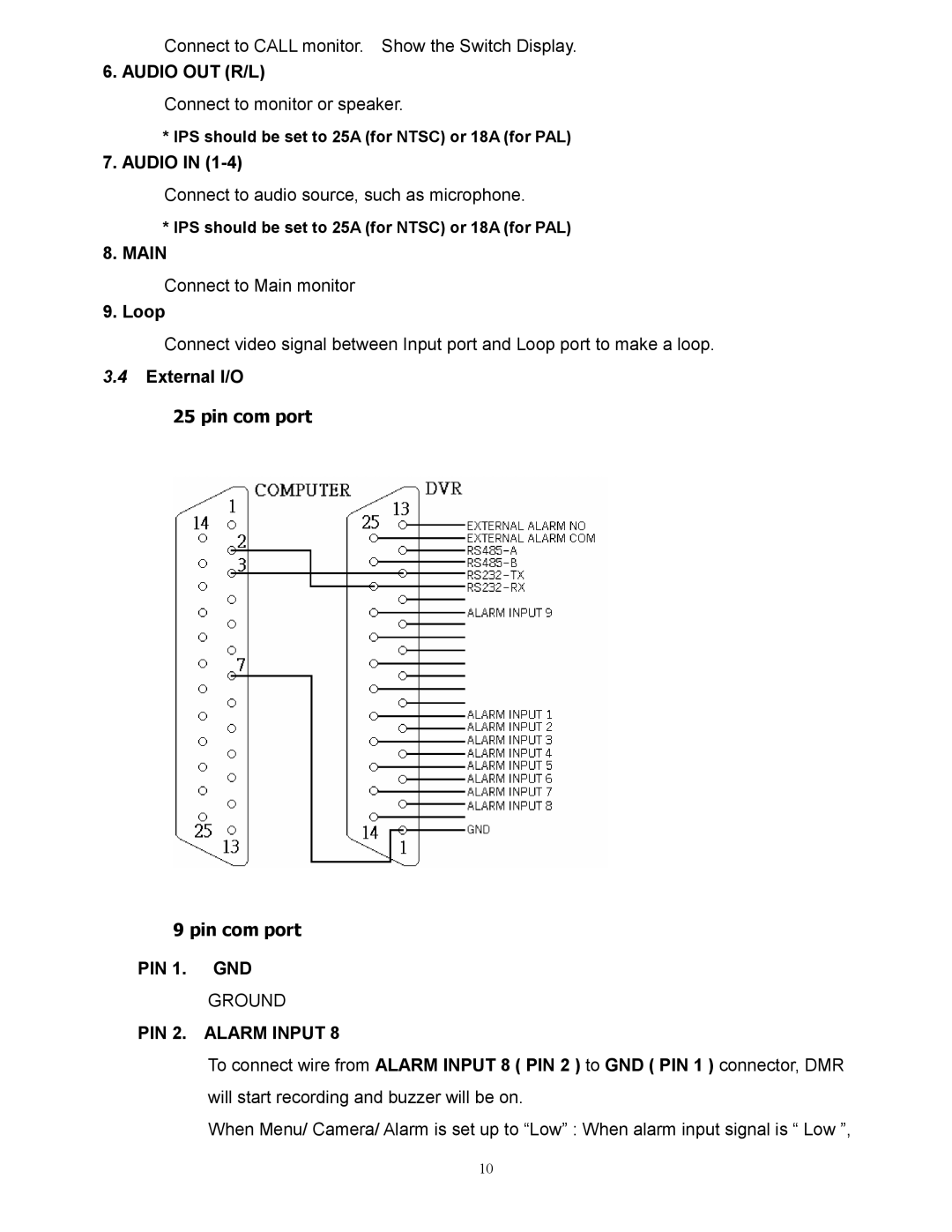
3.4External I/O
25 pin com port
9 pin com port
PIN 1. GND
GROUND
PIN 2. ALARM INPUT 8
To connect wire from ALARM INPUT 8 ( PIN 2 ) to GND ( PIN 1 ) connector, DMR will start recording and buzzer will be on.
When Menu/ Camera/ Alarm is set up to “Low” : When alarm input signal is “ Low ”,
10