PIN 21. PIN OFF
PIN 22. ALARM INPUT 9
To connect wire from ALARM INPUT 9 ( PIN 22 ) to GND ( PIN 1 ) connector, DMR
will start recording and buzzer will be on.
When Menu/ Camera/ Alarm is set up to “Low” : When alarm input signal is “ Low ”,
the unit starts to record and buzzer.
When Menu/ Camera/ Alarm is set up to “High” : When alarm input signal is “ High ”,
the unit starts to record and buzzer.
PIN 23.
DMR can be controlled remotely by an external device or control system, such as a
control keyboard, using
PIN 24.
DMR can be controlled remotely by an external device or control system, such as a
control keyboard, using RS485 serial communications signals.
PIN 25. EXTERNAL ALARM COM
Under normal operation COM disconnect with NO. But when alarm triggered, COM
connect with NO.
3.4Menu setup
Press ”MENU” to enter main menu. You will need to enter password to access main menu. To press “Right” “Left” to move digit, and Press ”Up” “Down” to select number.
Press ”ENTER” button to confirm password.
Ex.: Password : 0000 (Default : 0000)
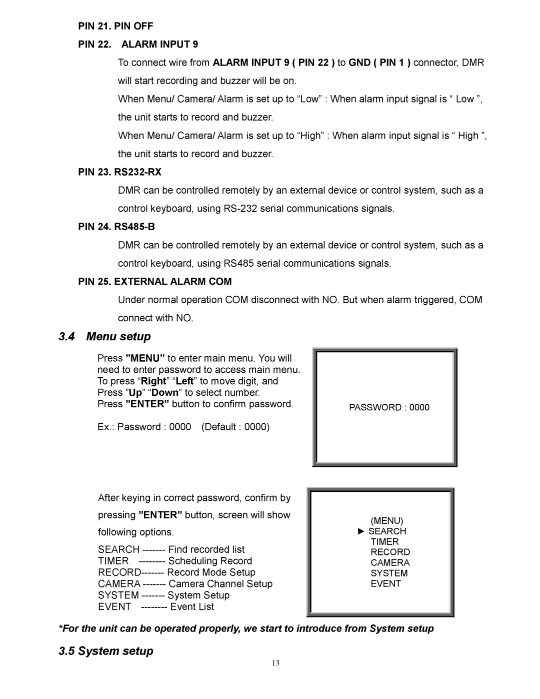
After keying in correct password, confirm by
pressing ”ENTER” button, screen will show
following options.
SEARCH | Find recorded list |
TIMER | Scheduling Record |
Record Mode Setup | |
CAMERA | Camera Channel Setup |
SYSTEM | System Setup |
EVENT | Event List |
PASSWORD : 0000
(MENU)
►SEARCH TIMER RECORD CAMERA SYSTEM EVENT
*For the unit can be operated properly, we start to introduce from System setup
3.5 System setup
13