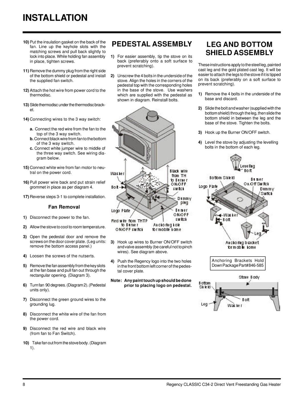
C34-LP2, C34-NG2 specifications
The Regency C34-LP2 and C34-NG2 are two exceptional offerings in the world of gas fireplaces, designed to bring both warmth and style to modern living spaces. These units are perfect for homeowners who appreciate the ambiance of a traditional fireplace but desire the convenience and efficiency of gas heating.Starting with the design, both the C34-LP2 and C34-NG2 feature a sleek and contemporary aesthetic, easily integrating into various interior styles. The clean lines and large viewing area provide an unobstructed view of the flames, creating a focal point in any room. The glass front complements the modern decor while emphasizing the natural flicker of firelight.
One of the standout features of the C34 series is the dual burner system, which allows for enhanced flame control and efficiency. The design offers an impressive flame pattern that can be adjusted to suit the user's preference, whether they seek a cozy, intimate setting or a more robust fire experience. This versatility is especially appealing for entertaining guests or creating a romantic atmosphere at home.
Technologically, both models are equipped with advanced features to optimize performance. The electronic ignition system ensures reliable lighting, while the precision flame adjustment allows users to easily manipulate heat levels. This adaptability can lead to significant energy savings, making the C34 series not only environmentally conscious but also cost-effective.
In terms of technical specifications, the C34-LP2 is designed for liquid propane, while the C34-NG2 runs on natural gas, providing flexibility depending on the homeowner's fuel availability. Both models possess impressive heating capabilities, with an output sufficient to warm larger spaces, making them ideal for living rooms, dining areas, or open-concept homes.
Safety is also a priority with the C34 series. Equipped with a safety shutoff system and a glass front that remains cool to the touch, these units are designed to provide peace of mind for families. The option for a remote control adds an additional layer of convenience, allowing users to adjust settings from across the room.
Overall, the Regency C34-LP2 and C34-NG2 unite modern innovation with traditional comfort. With their stunning design, advanced technology, and excellent heating efficiency, these gas fireplaces are a valuable addition to any home, enhancing both aesthetic and functional appeal.

