INSTALLATION
1)Remove the screw from the vent hole cover (vent cover 'A') on top of the unit.
2)Take the connector collar and press and rotate it into the hole to cut through the insulation layer. Remove the collar and removeinsulationfromthecollar.Thescrews for the inner cover should be exposed.
3)Remove the screws from the inner cover (vent cover 'B') and slide it back under the insulation.
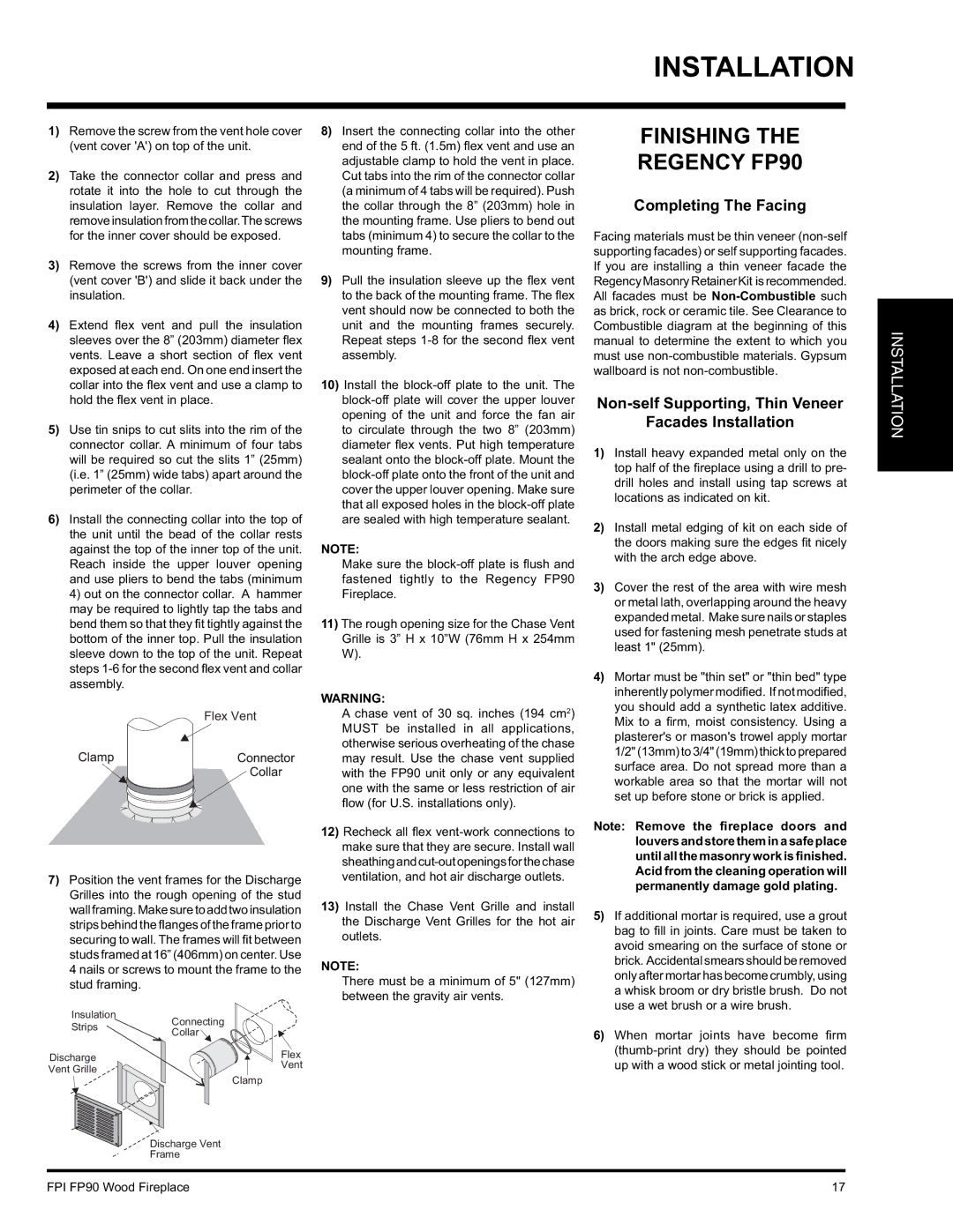
4)Extend fl ex vent and pull the insulation sleeves over the 8” (203mm) diameter fl ex vents. Leave a short section of fl ex vent exposed at each end. On one end insert the collar into the fl ex vent and use a clamp to hold the fl ex vent in place.
5)Use tin snips to cut slits into the rim of the connector collar. A minimum of four tabs will be required so cut the slits 1” (25mm) (i.e. 1” (25mm) wide tabs) apart around the perimeter of the collar.
6)Install the connecting collar into the top of the unit until the bead of the collar rests against the top of the inner top of the unit. Reach inside the upper louver opening and use pliers to bend the tabs (minimum 4) out on the connector collar. A hammer may be required to lightly tap the tabs and bend them so that they fit tightly against the bottom of the inner top. Pull the insulation sleeve down to the top of the unit. Repeat steps
Flex Vent
7)Position the vent frames for the Discharge Grilles into the rough opening of the stud wall framing. Make sure to add two insulation strips behind the flanges of the frame prior to securing to wall. The frames will fi t between studs framed at 16” (406mm) on center. Use 4 nails or screws to mount the frame to the stud framing.
Insulation
StripsConnecting
Collar
Discharge | Flex | |
Vent | ||
Vent Grille | ||
Clamp | ||
|
8)Insert the connecting collar into the other end of the 5 ft. (1.5m) fl ex vent and use an adjustable clamp to hold the vent in place. Cut tabs into the rim of the connector collar (a minimum of 4 tabs will be required). Push the collar through the 8” (203mm) hole in the mounting frame. Use pliers to bend out tabs (minimum 4) to secure the collar to the mounting frame.
9)Pull the insulation sleeve up the fl ex vent to the back of the mounting frame. The fl ex vent should now be connected to both the unit and the mounting frames securely. Repeat steps
10)Install the
NOTE:
Make sure the
11)The rough opening size for the Chase Vent Grille is 3” H x 10”W (76mm H x 254mm W).
WARNING:
A chase vent of 30 sq. inches (194 cm2) MUST be installed in all applications, otherwise serious overheating of the chase may result. Use the chase vent supplied with the FP90 unit only or any equivalent one with the same or less restriction of air
fl ow (for U.S. installations only).
12)Recheck all fl ex
13)Install the Chase Vent Grille and install the Discharge Vent Grilles for the hot air outlets.
NOTE:
There must be a minimum of 5" (127mm) between the gravity air vents.
FINISHING THE
REGENCY FP90
Completing The Facing
Facing materials must be thin veneer
Non-self Supporting, Thin Veneer
Facades Installation
1)Install heavy expanded metal only on the top half of the fireplace using a drill to pre- drill holes and install using tap screws at locations as indicated on kit.
2)Install metal edging of kit on each side of the doors making sure the edges fi t nicely with the arch edge above.
3)Cover the rest of the area with wire mesh or metal lath, overlapping around the heavy expanded metal. Make sure nails or staples used for fastening mesh penetrate studs at least 1" (25mm).
4)Mortar must be "thin set" or "thin bed" type inherently polymer modified. If not modified, you should add a synthetic latex additive. Mix to a firm, moist consistency. Using a plasterer's or mason's trowel apply mortar 1/2"(13mm)to3/4"(19mm)thicktoprepared surface area. Do not spread more than a workable area so that the mortar will not set up before stone or brick is applied.
Note: Remove the fireplace doors and louvers and store them in a safe place until all the masonry work is finished. Acid from the cleaning operation will permanently damage gold plating.
5)If additional mortar is required, use a grout bag to fi ll in joints. Care must be taken to avoid smearing on the surface of stone or brick. Accidental smears should be removed only after mortar has become crumbly, using a whisk broom or dry bristle brush. Do not use a wet brush or a wire brush.
6)When mortar joints have become fi rm
INSTALLATION
Discharge Vent Frame
FPI FP90 Wood Fireplace | 17 |