INSTALLATION
INSTALLATION
![]()
![]()
![]()
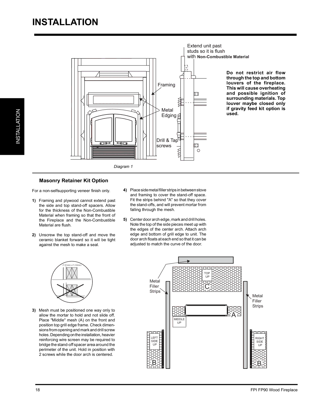
Do not restrict air flow through the top and bottom louvers of the fireplace. This will cause overheating and possible ignition of surrounding materials. Top louver maybe closed only if gravity feed kit option is used.
Diagram 1
Masonry Retainer Kit Option
For a
1)Framing and plywood cannot extend past the side and top
2)Unscrew the top
4)Place side metal filler strips in between stove and framing to cover the
5)Center door arch edge, mark and drill holes. Note the top of the side pieces meet up with the edges of the center arch. Attach arch edge and bottom of grill edge to unit. The door arch fl oats at each end so that it can be adjusted to match the curve of the door.
2" (51mm) x 4" (102mm)
3)Mesh must be positioned one way only to allow the mortar to hold and not slide off. Place "Middle" mesh (A) on the front and position top grill edge frame. Check dimen- sions from opening and mark and drill screw holes.Dependingontheinstallation,heavier reinforcing wire screen may be required to bridge the
Metal
Filler
Strips![]()
.
LEFT
SIDE
UP
B .
TOP
UP
C
. .. .
. | . | . . A |
|
|
MIDDLE
UP
.
![]() Metal
Metal
Filler
Strips
.
RIGHT
SIDE
UP
. B
18 | FPI FP90 Wood Fireplace |
