INSTALLATION
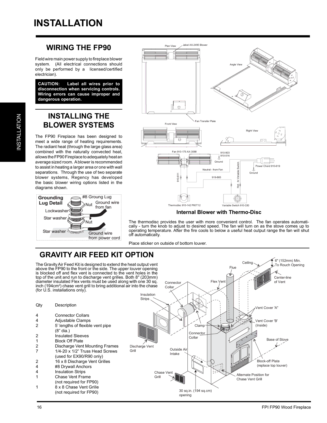
WIRING THE FP90
Field wire main power supply to fi replace blower system. (All electrical connections should only be performed by a licensed/certifi ed electrician).
CAUTION: Label all wires prior to disconnection when servicing controls. Wiring errors can cause improper and dangerous operation.
Plan View | Jakel |
Angle View
INSTALLATION
INSTALLING THE
BLOWER SYSTEMS
The FP90 Fireplace has been designed to meet a wide range of heating requirements. The radiant heat (through the large glass area) combined with the naturally convected heat, allows the FP90 Fireplace to adequately heat an average sized room. Ablower is recommended to assist in heating a larger area or one with wall separations. Through the use of two separate blower systems, Regency has developed the basic blower wiring options listed in the diagrams shown.
Fan Transfer Plate
Front View
|
| Right View | |
Fan |
|
| |
|
|
| |
|
|
| |
| Ground | Switch |
|
|
| Power Chord | |
Neutral - from Fan | Variableto |
| |
| Ground | ||
|
|
| |
|
|
| |
|
| Hot- |
|
Thermodisc | Variable Switch |
| |
Internal Blower with Thermo-Disc
The thermodisc provides the user with more convenient control. The fan operates automati- cally - turn the knob to adjust to desired speed. The fan will turn on as the stove comes up to operating temperature. After the fire cools to below a useful heat output range the fan will shut off automatically.
Place sticker on outside of bottom louver.
GRAVITY AIR FEED KIT OPTION
 6" (152mm) Min.
The Gravity Air Feed Kit is designed to extend the heat output vent above the FP90 to the front or the side. The upper louver opening is blocked off and fl ex vent is connected to the vent holes in the
Ceiling
Flue
To Rouch Opening
top of the unit and run to discharge vent grilles. Both 8" (203mm) diameter insulated Flex vents must be used along with one 30 sq. inch (194cm2) chase vent grill to bring additional air into the chase (for U.S. installations only).
Insulation
Strips
Qty Description
4Connector Collars
4Adjustable Clamps
25’ lengths of fl exible vent pipe (8” dia.)
2Insulated Sleeves
1 | Block Off Plate |
|
2 | Discharge Vent Mounting Frames | Discharge Vent |
7 | Grill | |
| (used for EX90/R90 only) |
|
Connector
Collar
Outside Air Intake
| |
Flex Vent | of Vent |
| Vent Cover 'A" |
| Vent Cover 'B' |
Clamp | (Inside) |
Connector |
|
Collar | Base of Stove |
|
216 x 8 Discharge Vent Grilles
4#8 Drywall Anchors
4 | Insulation Strips | Chase Vent |
1 | Chase Vent Frame | Grill |
| (not required for FP90) |
|
18 x 8 Chase Vent Grille
(replace top louver) |
Alternate Position for |
Chase Vent Grill |
(not required for FP90) | 30 sq.in. (194 sq.cm) | |
opening | ||
|
16 | FPI FP90 Wood Fireplace |