Or maintenance can result in death, injury or
Improper installation, adjustment, alteration, service
Property damage. Read the Installation, Operation
Installation must be done by a contractor qualified
Page
Roberts-Gordon LLC
Page
Table of Figures
Page
Manpower Requirements
Heater Safety
Safety Labels and Their Placement
California Proposition
Top and Bottom Panel Label Placement
Side and Back Panel Label Placement
National Standards and Applicable Codes
Installer Responsibility
Wall Tag
Clearances are the required distances that
Maintain clearances to combustibles at all times for safety
C D
Inches
Centimeters
Model
Tube, Standard Reflector Model
45 Tilt Reflector Model
Inches Centimeters
Tube, Opposite 45 Reflector Model
Centimeters Model
Venting Inches
National Standards and Applicable Codes
Stainless Steel
Major Components
Burner Tube
Reflector End Cap
Contents of Core and Extension Packages
Standard Parts List
Contents of BH-Series Burner Carton
BH-Series Component Package Guide Model Tubing Length
Core Packages Minimum Standard Aluminized
Heater Installation
Typical Suspension Details
Linear Heater Assembly Overview
Linear Heater Layout Overview
Linear Heater Layout Overview
Burner Tube Installation
Coupling and Tube Assembly
Tube Clamp Package Installation
Open
Closed
2 Coupling and Tube Assembly
1 Coupling and Tube Assembly
Not required on the BH-125/150/175/200
Turbulator Installation
Hanger Burner Tube Reflector
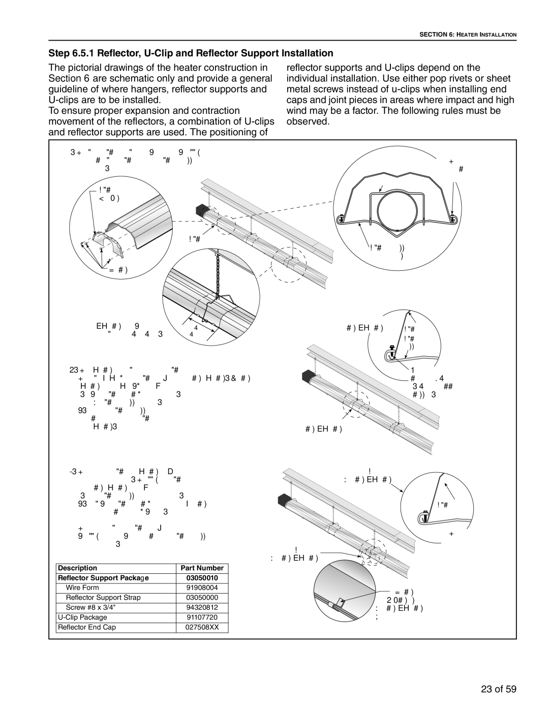
Description Part Number Reflector Support Package
1 Reflector, U-Clip and Reflector Support Installation
Burner Installation
Optional Heater Accessories
Tube, Opposite
Tube, Standard
Tube
Tube Heater Layout Overview
Tube Layout Overview
Elbow Package Configuration .2.1 Elbow Installation
2 Elbow Installation
Reflector Joint Detail
5 Reflector Joint Detail
2 Side Reflector Installation
Reflector Side Extension 1 Bracket Installation
Description Part Number Lower Clearance Shield Package
Distance a Extension
2 Frame Shield Installation
3 Grille Installation
2 Grille End Cap Installation
Canadian Requirements
Venting
United States Requirements
Horizontal Venting
Unvented Operation
Vertical Venting
Unvented Operation Tube Termination
Outside Wall
Vertical Ventilation 4 10 cm Pipe
Common Side Wall Venting
Common Vertical Venting
Outside Combustion Air Supply
Vertical Outside Air Supply for Single Heater Installation
Horizontal Outside Air Supply for Double Heater Installation
Vertical Outside Air Supply for Double Heater Installation
GAS Piping
Correct Positions
When attaching gas hose
Hold gas nipple securely with pipe wrench
Failure to follow these instructions can result
Line Voltage Thermostat Wiring
Wiring
Front View
Low Voltage Thermostat Wiring
Internal Wiring
Ladder Diagram Electrical Connection to the Burner
Pre-Season Maintenance and Annual Inspection
Operation and Maintenance
Sequence of Operation
To Shut Off Heater
Vehicles and Other
Vicinity of the Heater
Objects
Reflector
Blower Scroll, Wheel
Safety Labels
Motor Burner Cup and Orifice
Electrode
Troubleshooting
YES
Troubleshooting Flow Chart
Page
Manifold Gas Pressure Setting
Replacement Parts
Replacement Parts
Description Part Number
Dimensions
General Specifications
GAS Pressure AT Manifold
Pipe Connection
Page
ROBERTS-GORDON LLC will PAY for
Warranty is Void if
ROBERTS-GORDON LLC will not PAY for
Limitations on Authority Representatives
Page
Page
Page