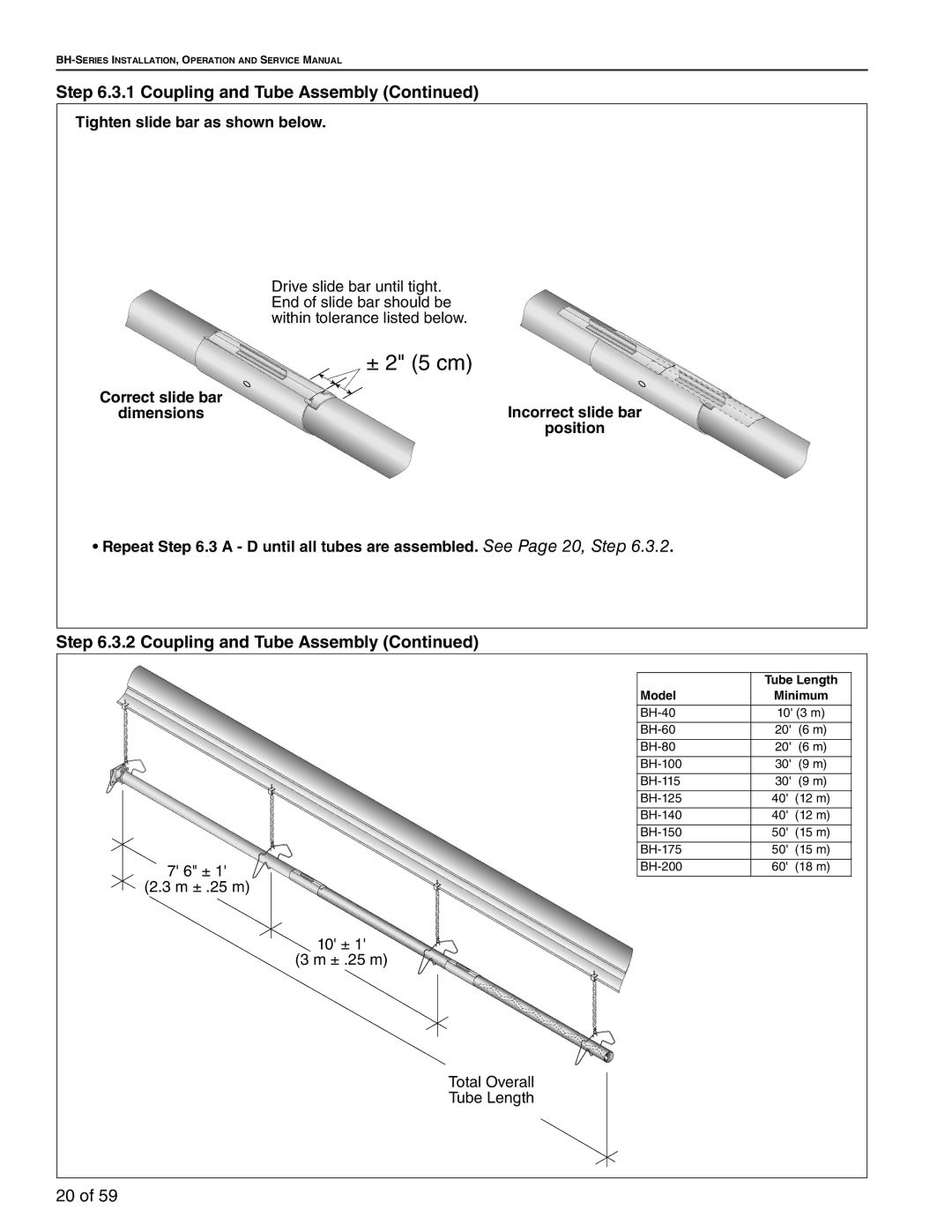
Step 6.3.1 Coupling and Tube Assembly (Continued)
Tighten slide bar as shown below.
| Drive slide bar until tight. |
| End of slide bar should be |
| within tolerance listed below. |
| ± 2" (5 cm) |
Correct slide bar | Incorrect slide bar |
dimensions | |
| position |
• Repeat Step 6.3 A - D until all tubes are assembled. See Page 20, Step 6.3.2.
Step 6.3.2 Coupling and Tube Assembly (Continued)
7' 6" ± 1' 
 (2.3 m ± .25 m)


10' ± 1'
(3 m ± .25 m)
| Tube Length |
Model | Minimum |
|
|
10' (3 m) | |
|
|
20' (6 m) | |
|
|
20' (6 m) | |
|
|
30' (9 m) | |
|
|
30' (9 m) | |
|
|
40' (12 m) | |
|
|
40' (12 m) | |
|
|
50' (15 m) | |
|
|
50' (15 m) | |
|
|
60' (18 m) | |
|
|
Total Overall Tube Length
20 of 59
