SECTION 8: UNITARY LINEAR &
8.4 Unitary U-tube Heater Layouts
The
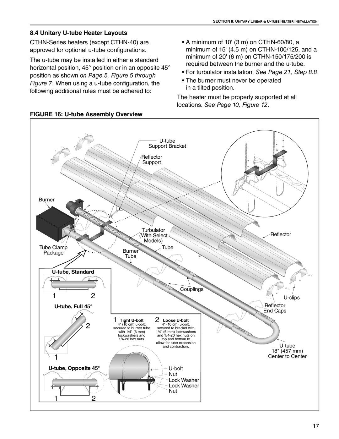
FIGURE 16: U-tube Assembly Overview
•A minimum of 10' (3 m) on
•For turbulator installation, See Page 21, Step 8.8.
•The burner must never be operated in a tilted position.
The heater must be properly supported at all locations. See Page 10, Figure 12.
Support Bracket
Reflector
Support
Burner
Turbulator
(With Select
Reflector
Tube Clamp
Package
Burner
Tube
Models) Tube
12
U-tube, Full 45°
2
1
U-tube, Opposite 45°
12
|
| Couplings |
1 | Tight | Loose |
4" (10 cm) | 2 4" (10 cm) | |
secured to burner tube | secured to bracket with | |
| with 1/4" (6 mm) | 1/4" (6 mm) lockwashers |
| lockwashers and | and |
| top and bottom to | |
|
| allow for tube expansion |
|
| and contraction. |
|
| |
|
| Nut |
|
| Lock Washer |
|
| Lock Washer |
|
| Nut |
 U-clips
Reflector
End Caps
U-tube
18" (457 mm)
Center to Center
17