SECTION 9: MULTIBURNER HEATER INSTALLATION
9.6.3Herringbone Layout and Manifold Tube Length Rules
The herringbone layout is essentially several T layouts stacked together. Therefore, the same principle for manifold tube calculation as used for T layouts is used for herringbone layouts, with one exception. In a herringbone layout, the manifold tube length between tees (or crosses) as well as between the last tee (or cross) and the pump is calculated by dividing by 1.5 as shown in the T example on Page 33, Section 9.6.2. The only manifold tube length in a herringbone layout that is not divided by 1.5 is any manifold tube length located between the end of the radiant tube and a tee or cross.
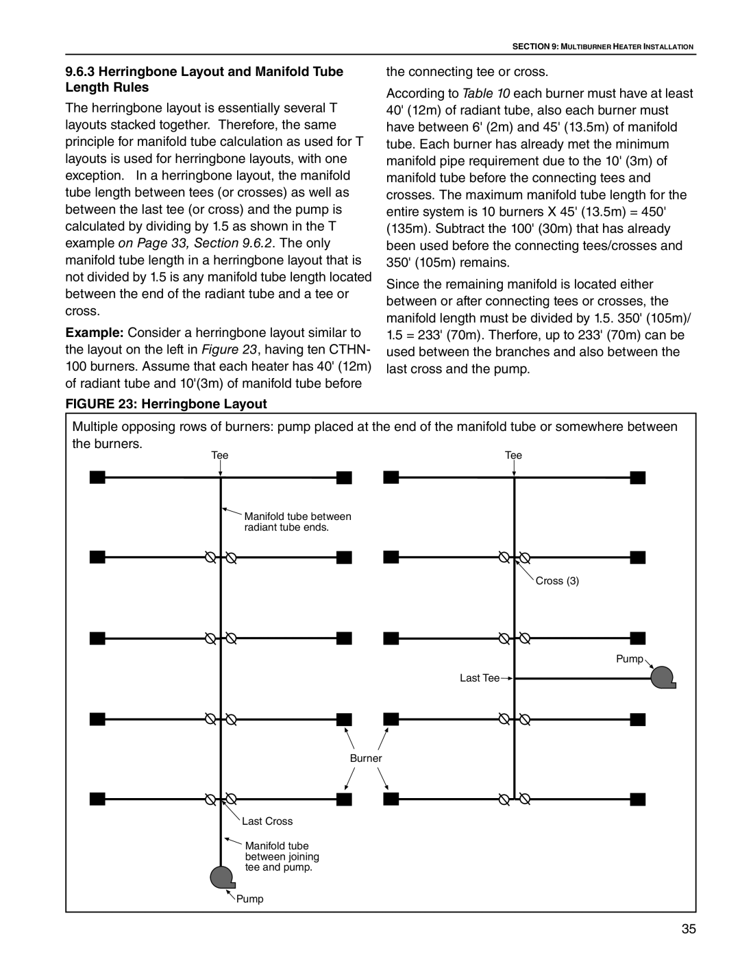
Example: Consider a herringbone layout similar to the layout on the left in Figure 23, having ten CTHN- 100 burners. Assume that each heater has 40' (12m) of radiant tube and 10'(3m) of manifold tube before
FIGURE 23: Herringbone Layout
the connecting tee or cross.
According to Table 10 each burner must have at least 40' (12m) of radiant tube, also each burner must have between 6' (2m) and 45' (13.5m) of manifold tube. Each burner has already met the minimum manifold pipe requirement due to the 10' (3m) of manifold tube before the connecting tees and crosses. The maximum manifold tube length for the entire system is 10 burners X 45' (13.5m) = 450' (135m). Subtract the 100' (30m) that has already been used before the connecting tees/crosses and 350' (105m) remains.
Since the remaining manifold is located either between or after connecting tees or crosses, the manifold length must be divided by 1.5. 350' (105m)/
1.5= 233' (70m). Therfore, up to 233' (70m) can be used between the branches and also between the last cross and the pump.
Multiple opposing rows of burners: pump placed at the end of the manifold tube or somewhere between the burners.
Tee | Tee |
| Manifold tube between |
| radiant tube ends. |
| Cross (3) |
| Pump |
| Last Tee |
| Burner |
![]() Last Cross
Last Cross
![]() Manifold tube between joining tee and pump.
Manifold tube between joining tee and pump.
![]() Pump
Pump
35