Step 9.9.2 Coupling and Tube Assembly (Continued)
|
|
| Radiant |
|
| Model | Tube Length |
|
| 10' (4.5 m) | |
|
| 20' (6 m) | |
|
| 20' (6 m) | |
|
| 30' (9 m) | |
|
| 40' (12 m) | |
|
| 40' (12 m) | |
|
| 50' (18 m) | |
|
| 50' (18 m) | |
2.3 m | .25 m |
|
|
| 3 m | .25 m |
|
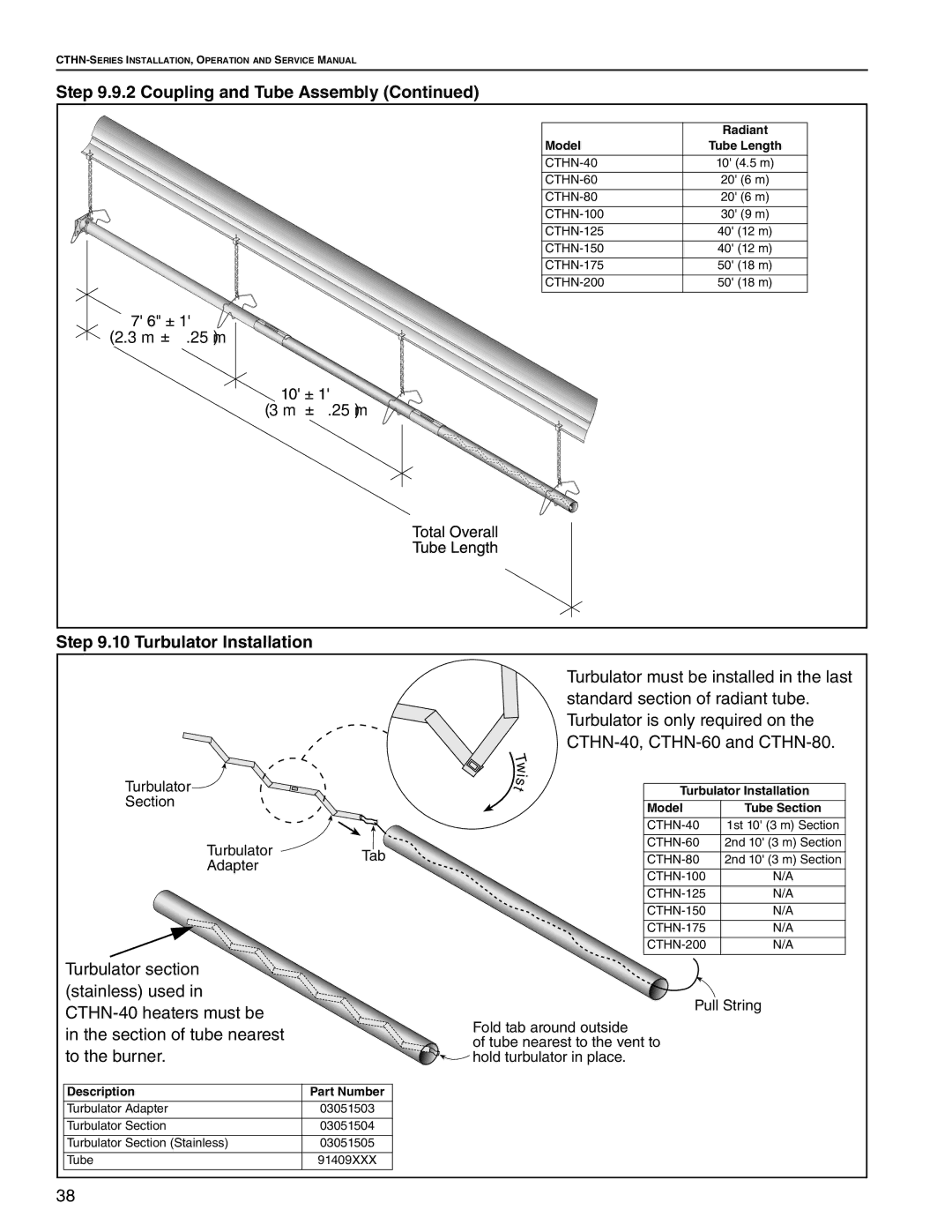
Step 9.10 Turbulator Installation
Turbulator![]()
Section
TurbulatorTab
Adapter
Turbulator section ![]() (stainless) used in
(stainless) used in
in the section of tube nearest to the burner.
Description | Part Number |
Turbulator Adapter | 03051503 |
|
|
Turbulator Section | 03051504 |
|
|
Turbulator Section (Stainless) | 03051505 |
|
|
Tube | 91409XXX |
|
|
Turbulator must be installed in the last standard section of radiant tube. Turbulator is only required on the
T |
|
|
w |
|
|
i |
|
|
s |
|
|
t | Turbulator Installation | |
| Model | Tube Section |
|
|
|
| 1st 10' (3 m) Section | |
|
|
|
| 2nd 10' (3 m) Section | |
|
|
|
| 2nd 10' (3 m) Section | |
|
|
|
| N/A | |
|
|
|
| N/A | |
|
|
|
| N/A | |
|
|
|
| N/A | |
|
|
|
| N/A | |
|
|
|
Pull String
Fold tab around outside
of tube nearest to the vent to ![]()
![]() hold turbulator in place.
hold turbulator in place.
38