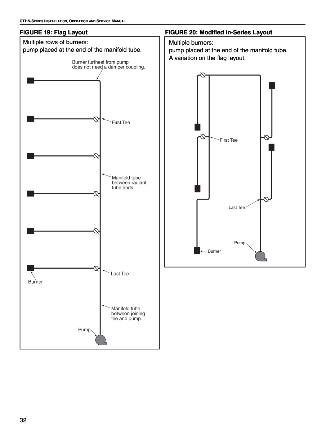
FIGURE 19: Flag Layout
Multiple rows of burners:
pump placed at the end of the manifold tube.
Burner furthest from pump
does not need a damper coupling.
![]() First Tee
First Tee
![]() Manifold tube between radiant tube ends.
Manifold tube between radiant tube ends.
![]()
![]() Last Tee Burner
Last Tee Burner
![]() Manifold tube between joining tee and pump.
Manifold tube between joining tee and pump.
Pump
FIGURE 20: Modified In-Series Layout
Multiple burners:
pump placed at the end of the manifold tube. A variation on the flag layout.
![]() First Tee
First Tee
Last Tee ![]()
Pump
![]()
![]()
![]() Burner
Burner
32