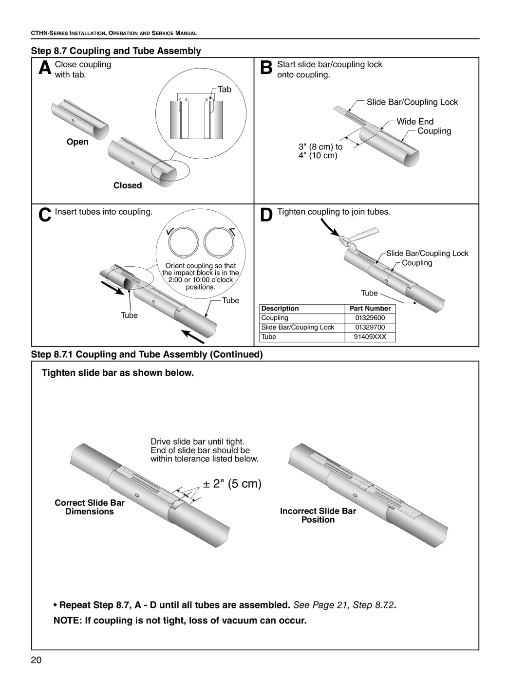
Step 8.7 Coupling and Tube Assembly
Close coupling | Start slide bar/coupling lock |
A with tab. | B onto coupling. |
| Tab |
| |
|
| Slide Bar/Coupling Lock | |
|
| Wide End | |
|
| Coupling | |
Open | 3" (8 cm) to |
| |
|
| ||
| 4" (10 cm) |
| |
Closed |
|
| |
C Insert tubes into coupling. | D Tighten coupling to join tubes. | ||
|
| Slide Bar/Coupling Lock | |
| Orient coupling so that | Coupling | |
| the impact block is in the |
| |
| 2:00 or 10:00 o’clock |
| |
| positions. | Tube | |
| Tube | ||
|
| ||
Tube | Description | Part Number | |
Coupling | 01329600 | ||
| |||
| Slide Bar/Coupling Lock | 01329700 | |
| Tube | 91409XXX | |
Step 8.7.1 Coupling and Tube Assembly (Continued)
Tighten slide bar as shown below.
| Drive slide bar until tight. |
| End of slide bar should be |
| within tolerance listed below. |
| ± 2" (5 cm) |
Correct Slide Bar | Incorrect Slide Bar |
Dimensions | |
| Position |
•Repeat Step 8.7, A - D until all tubes are assembled. See Page 21, Step 8.7.2.
NOTE: If coupling is not tight, loss of vacuum can occur.
20