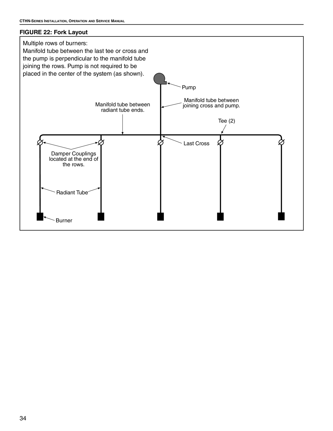
FIGURE 22: Fork Layout
Multiple rows of burners:
Manifold tube between the last tee or cross and the pump is perpendicular to the manifold tube joining the rows. Pump is not required to be placed in the center of the system (as shown).
Manifold tube between
radiant tube ends.
Damper Couplings located at the end of the rows.
![]() Radiant Tube
Radiant Tube
![]()
![]()
![]() Burner
Burner
![]() Pump
Pump
Manifold tube between ![]() joining cross and pump.
joining cross and pump.
Tee (2)
![]()
![]() Last Cross
Last Cross
34