Manuals
/
Samsung
/
Computer Equipment
/
Printer
Samsung
SCX-4100
specifications
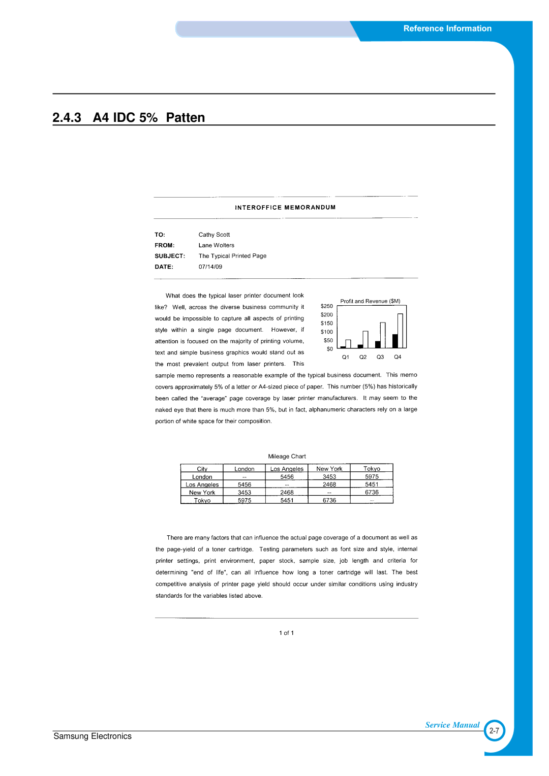
3 A4 IDC 5% Patten
Models:
SCX-4100
1
14
111
111
Download
111 pages
56.17 Kb
11
12
13
14
15
16
17
18
Troubleshooting
Specifications
Parts list
Block Diagram
Fuser Error
Copy Problems
Diagnostic
Main Assembly
Precautions
Safety
Page 14
Image 14
Reference Information
2.4.3 A4 IDC 5% Patten
Service Manual
Samsung Electronics
2-7
Page 13
Page 15
Page 14
Image 14
Page 13
Page 15
Contents
Troubleshooting
Precautions
Specifications
Block Diagram
Http//itself.sec.samsung.co.kr
Precautions
Safety Warning
Electric Shock and Fire Safety Precautions
Toxic material
Handling Precautions
Assembly / Disassembly Precautions
Be careful with the high temperature part
Disregarding this warning may cause bodily injury
ESD Precautions
Tool for Troubleshooting
Acronyms and Abbreviations
IPC
Select a location for the printer
Sample Pattern for the Test
1 A4 5% Pattern
2 A4 2% Pattern
3 A4 IDC 5% Patten
Memo
Specifications
General Specifications
Print Specification
Scan Specification
Copy Specification
Copy
Paper Handiling Specification
Other Specification
Whql
Memo
Printer Components
Front View
Rear View
Control Panel
System Layout
Drive Ass’y
Paper Feed Mechanism
Transfer Ass’y
Fixing PartFuser
Scan Image Controller
Safety Relevant Facts
Scanner Unit
CIS Driver Circuit
LSU Laser Scanner Unit
Toner Cartridge
Main PBA
Sdram
Asic Chorus2
Flash Memory
Sensor input circuit
Cover Open Sensing
Paper Feeding, Toner Cartridge Sensing
Paper Exit Sensing
DC FAN / Solenoid Driver
Smps & Hvps
HVPSHigh Voltage Power Supply
Consumption Power
Smps Switching Mode Power Supply
Rated Power Output
Length of Power Cord 1830 ± 50mm Power Switch Fitted
Environment Condition
Fuser AC Power Control
Feature
Safty Requrement
Transfer
Engine F/W
Drive
Feeding
Heat Lamp Method
Fusing
5 LSU
Memo
Whenever servicing the machine, you must perform as follows
General Precautions on Disassembly
Releasing Plastic Latches
Front and Rear Cover Units
Side Covers
Scanner Ass’y
Remove Scanner Ass’y
Dismantle Scanner Ass’y
Spring Pulley Idle ETC Belt
Middle Cover
FuserHeat Lamp Type
Remove 4 screws and divide the Fuser into two parts
Exit Roller
LSU
Fan
Engine Shield Ass’y
Smps
Transfer Roller
Feed Roller
Remove the Feed Roller and Feed Roller1, as shown below
Pick Up Roller & Solenoid
Memo
Diagnostic
Engine Test Mode
To enter the Engine Test Mode
To enter the Engine Test mode
Paper Path
Clearing Paper Jams
Paper Tray
Paper Exit Area
Fuser Area or Around the Toner Cartridge
Manual Feeder
Clearing the Drum
Printing the System Data List
Clearing the Memory
Consumables and Replacement Parts
LCD Status Display by Each Error
Periodic Defective Image
Roller Defective image Typical defect
Vertical White Line
Printing Problems Causes and Solutions
Vertical Black Lines and Bands
Horizontal Black Bands
Black/White Spot
Light Image
Dark Image or a Black
Uneven Density
Background
Ghost
Stains on the Face
Digital Printer Ghost
Stains on Back
Blank Page Print out
Black Copy
Copy Problems
White Copy
Abnormal noise
Defective Image Quality
2 JAM
Paper Feed problems Causes and Solutions
Wrong Print Position
3 JAM
4 JAM
Multi-Feeding
Paper rolled in the fuser
Paper rolled on the OPC Drum
LSU Error
Printer Faults Causes and Solutions
Fuser Error
Fuser gear melts due to overheating causing Paper Jam
Paper Empty
Paper Empty without indication
Cover Open
No error message when the cover is open
No Power
Defective motor operation
Printed Vertical Lines become curved
Service for the Life of Toner Cartridge
Toner Cartridge Service
Precautions on Safe-keeping of Toner Cartridge
Standard of guarantee for consumable parts
Signs and Measures of Poor toner cartridge
Ended
Fault Signs Cause & Check Solution
Fault Signs Cause & Check Solution Ghost & Image
Software Problems Causes and Solutions
Printer is not working
Not working with the message insufficient printer
Abnormal Printing
Spool Error
How to delete the data in the spool manager
Memo
Exploded Views and Parts List
Main Assembly
Main Assembly Parts List
Frame Assembly
Frame Unit Assembly Parts List
Description SEC.Code ’ty Remark
Frame Unit Assembly Parts ListCont
Scanner Unit Assembly
Scanner Unit Assembly Parts List
Fuser Unit Assembly
Fuser Unit Assembly Parts List
WASHER-PLAIN
Middle Cover Unit Assembly
Middle Cover Unit Assembly Parts List
’ty Remark
Drive Unit Assembly
Drive Unit Assembly Parts List
Cassette Unit Assembly
Cassette Unit Assembly Parts List
Block Diagram
10.10Connection Diagram
Top
Page
Image
Contents