DE specifications
Sanyo DE is an innovative line of home appliances and electronics that showcases Sanyo's commitment to quality, efficiency, and user-centered design. This series includes various products, such as air conditioners, refrigerators, and microwaves, all engineered to enhance the everyday living experience.One of the standout features of Sanyo DE appliances is their energy efficiency. Many models are equipped with advanced technologies that adhere to stringent energy-saving standards, helping consumers reduce their electricity bills while minimizing their environmental footprint. The use of inverter technology in air conditioners, for instance, allows for precise temperature control and significant reductions in energy consumption.
Sanyo DE also emphasizes smart technology integration. Many products come with Wi-Fi capabilities, enabling users to control their appliances remotely via mobile apps. This connectivity makes it easier to monitor energy usage, adjust settings, and receive alerts about maintenance needs. Users can enjoy added convenience as they can pre-heat their ovens or set their air conditioners to the desired temperature before arriving home.
Another key characteristic of Sanyo DE is its focus on durability and reliability. Each product is built with high-quality materials and undergoes rigorous testing to ensure long-lasting performance. The robust construction not only enhances the lifespan of the appliances but also provides peace of mind to users concerning their safety and functionality.
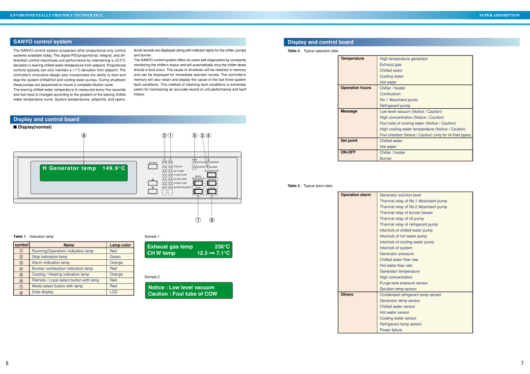
In terms of design, Sanyo DE products are crafted to blend seamlessly into modern homes with sleek and contemporary aesthetics. The intuitive user interfaces are designed for ease of use, featuring clear displays and simple controls, allowing users of all ages to operate the appliances without any hassle.
Furthermore, Sanyo DE pays attention to noise reduction. Many appliances incorporate sound dampening technologies, making them ideal for use in residential settings, where quiet operation is critical. Whether it’s a refrigerator running seamlessly in the background or an air conditioner cooling the room without disruption, Sanyo DE ensures a pleasant home atmosphere.
Overall, Sanyo DE exemplifies a fusion of advanced technology, energy efficiency, and user-friendly design. With a diverse range of appliances, Sanyo DE is committed to enhancing the lives of its users through thoughtful innovation and reliable performance.

