ENVIRONMENTALLY FRIENDLY TECHNOLOGY

Field wiring (DE)

SUPER ABSORPTION

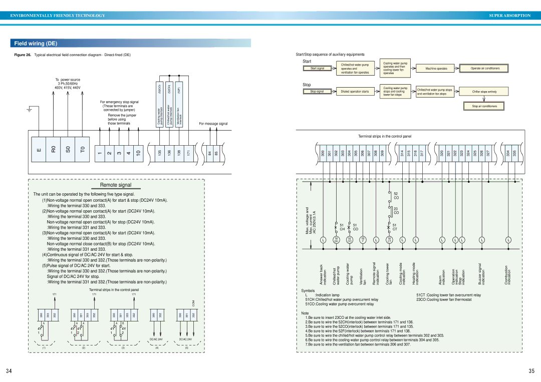
Figure 26. Typical electrical field connection diagram - Direct-fired (DE)

To power source


3 Ph,50/60Hz


(52CO)


(52CH)


(52F)


400V, 415V, 440V


For emergency stop signal


(Those terminals are

Coolingwater interlockpump


Chilled/hotwater interlockpump


Ventilationfan interlock


For message signal

those terminals


connected by jumper)


Remove the jumper


before using


Start/Stop sequence of auxiliary equipments

Start


Chilled/hot water pump


Start signal


operates and


ventilation fan operates


Stop


Stop signal


Diluted operation starts


Cooling water pump operates and then cooling tower fan operates

Cooling water pump stops and cooling tower fan stops

Machine operates

Chilled/hot water pump stops and ventilation fan stops

Operate air conditioners

Chiller stops entirely

Stop air conditioners

E

R0

S0

T0

1

2

3

4

10

135

136

138

171

84

85

Remote signal

The unit can be operated by the following five type signal.

(1)Non-voltage normal open contact(A) for start & stop (DC24V 10mA). :Wiring the terminal 330 and 333.

(2)Non-voltage normal open contact(A) for start (DC24V 10mA). :Wiring the terminal 330 and 333.

Non-voltage normal open contact(A) for stop (DC24V 10mA). :Wiring the terminal 331 and 333.

(3)Non-voltage normal open contact(A) for start (DC24V 10mA).

Terminal strips in the control panel

300

301

302

303

304

305

306

307

308

309


314

315

316

317


320

321

322

323

324

325

326

327


334

335


52


CO

voltageMax.and currentMax. 250V,0.1A:AC


23


CO


51

51

51


CH

CO

CT

:Wiring the terminal 330 and 333.

Non-voltage normal close contact(B) for stop (DC24V 10mA). :Wiring the terminal 331 and 333.

(4)Continuous signal of DC/AC 24V for start & stop.

:Wiring the terminal 330 and 332.(Those terminals are non-polarity.) (5)Pulse signal of DC/AC 24V for start.

:Wiring the terminal 330 and 332.(Those terminals are non-polarity.) Signal of DC/AC 24V for stop.

:Wiring the terminal 331 and 332.(Those terminals are non-polarity.)

Terminal strips in the control panel

171

171

171


COM

L

52

52

52

L

CH

CO

F

Answer back indication

Chilled/hot water pump

Cooling water pump

Ventilation fan

Remote signal indication

Symbols

L :Indication lamp

51CH:Chilled/hot water pump overcurrent relay 51CO:Cooling water pump overcurrent relay

52

CT L

Cooling tower fan

Cooling mode indication

LL L LL

Heating mode indication

Alarm indication

Operation indication Stop indication

Buzzer signal indication

51CT :Cooling tower fan overcurrent relay 23CO:Cooling tower fan thermostat

L

Combustion indication

330

333

332

330

331

333

332

330

331

333

332

330

332

330

331

332


A


A

A


A


B


4Y


4Y

4Y


4Y


4Y


1


1

2


1


2


DC/AC 24V

DC/AC 24V


(1)


(2)


(3)


(4)


(5)


Note

1.Be sure to insert 23CO at the cooling water inlet side.

2.Be sure to wire the 52CH(interlock) between terminals 171 and 136. 3.Be sure to wire the 52CO(interlock) between terminals 171 and 135. 4.Be sure to wire the 52F(interlock) between terminals 171 and 138.

5.Be sure to wire the chilled/hot water pump control relay between terminals 302 and 303. 6.Be sure to wire the cooling water pump control relay between terminals 304 and 305. 7.Be sure to wire the ventilation fan between terminals 306 and 307.

34

35

Page 19
Image 19
Sanyo operation manual Field wiring DE, Start, Stop

DE specifications

Sanyo DE is an innovative line of home appliances and electronics that showcases Sanyo's commitment to quality, efficiency, and user-centered design. This series includes various products, such as air conditioners, refrigerators, and microwaves, all engineered to enhance the everyday living experience.

One of the standout features of Sanyo DE appliances is their energy efficiency. Many models are equipped with advanced technologies that adhere to stringent energy-saving standards, helping consumers reduce their electricity bills while minimizing their environmental footprint. The use of inverter technology in air conditioners, for instance, allows for precise temperature control and significant reductions in energy consumption.

Sanyo DE also emphasizes smart technology integration. Many products come with Wi-Fi capabilities, enabling users to control their appliances remotely via mobile apps. This connectivity makes it easier to monitor energy usage, adjust settings, and receive alerts about maintenance needs. Users can enjoy added convenience as they can pre-heat their ovens or set their air conditioners to the desired temperature before arriving home.

Another key characteristic of Sanyo DE is its focus on durability and reliability. Each product is built with high-quality materials and undergoes rigorous testing to ensure long-lasting performance. The robust construction not only enhances the lifespan of the appliances but also provides peace of mind to users concerning their safety and functionality.

In terms of design, Sanyo DE products are crafted to blend seamlessly into modern homes with sleek and contemporary aesthetics. The intuitive user interfaces are designed for ease of use, featuring clear displays and simple controls, allowing users of all ages to operate the appliances without any hassle.

Furthermore, Sanyo DE pays attention to noise reduction. Many appliances incorporate sound dampening technologies, making them ideal for use in residential settings, where quiet operation is critical. Whether it’s a refrigerator running seamlessly in the background or an air conditioner cooling the room without disruption, Sanyo DE ensures a pleasant home atmosphere.

Overall, Sanyo DE exemplifies a fusion of advanced technology, energy efficiency, and user-friendly design. With a diverse range of appliances, Sanyo DE is committed to enhancing the lives of its users through thoughtful innovation and reliable performance.