Example: Basic Antenna/Cable Connections
DVD recorder | RFOUTPUT CHANNEL |
| |
(Partial back panel) | |
| OUTPUTRF CHANNEL |
1 | 3 |
4 | |
ANTENNA | |
or |
|
IN | OUT |
| |
antenna cable (not supplied)
3
42
AV 1 IN
VIDEO
L
VHF/UHF
R ![]() ANTENNA
ANTENNA
IN
TV
Cable TV wall jack
3
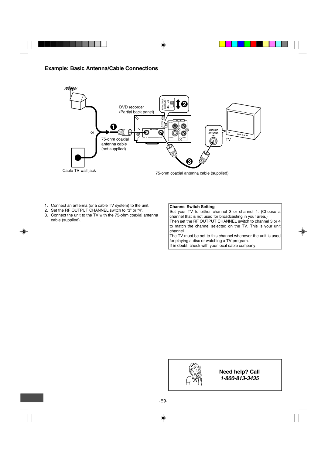
1.Connect an antenna (or a cable TV system) to the unit.
2.Set the RF OUTPUT CHANNEL switch to “3” or “4”.
3.Connect the unit to the TV with the
Channel Switch Setting
Set your TV to either channel 3 or channel 4. (Choose a channel that is not used for broadcasting in your area.)
Then set the RF OUTPUT CHANNEL switch to channel 3 or 4 to match the channel selected on the TV. This is your unit channel.
The TV must be set to this channel whenever the unit is used for playing a disc or watching a TV program.
If in doubt, check with your local cable company.
Need help? Call