Appendix
Optional Parts
The parts listed below are optionally available. When ordering those parts, specify the item name and Model No. to the sales dealer.
| Model No. |
: | |
: | |
: | |
TERMINAL COVER | : |
The Terminal Panel Replacement
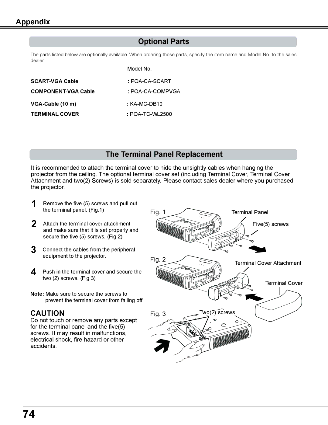
It is recommended to attach the terminal cover to hide the unsightly cables when hanging the projector from the ceiling. The optional terminal cover set (including Terminal Cover, Terminal Cover Attachment and two(2) Screws) is sold separately. Please contact sales dealer where you purchased the projector.
1
Fig. 1
2 | Attach the terminal cover attachment |
|
| and make sure that it is set properly and |
|
| secure the five (5) screws. (Fig 2) |
|
3 | Connect the cables from the peripheral |
|
| equipment to the projector. | Fig. 2 |
|
| |
4 | Push in the terminal cover and secure the |
|
| two (2) screws. (Fig 3) |
|
Note: Make sure to secure the screws to |
| |
| prevent the terminal cover from falling off. |
|
CAUTION | Fig. 3 | |
Do not touch or remove any parts except for the terminal panel and the five(5) screws. It may result in malfunctions, electrical shock, fire hazard or other accidents.
Terminal Panel
Five(5) screws
Terminal Cover Attachment
Terminal Cover
Two(2) screws
74
