|
|
|
|
|
|
|
| Unit 2: Technical Data |
|
| ||||
|
|
|
|
|
|
|
|
|
|
|
|
|
| |
|
|
|
|
|
|
|
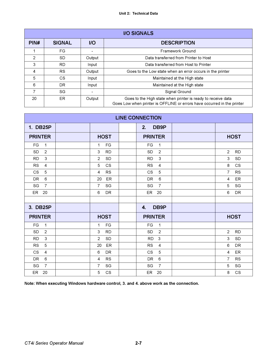
| I/O SIGNALS |
|
|
|
| ||
|
|
|
|
|
|
|
|
|
|
|
|
|
|
|
PIN# |
| SIGNAL | I/O |
|
|
|
|
| DESCRIPTION |
|
| |||
|
|
|
|
|
|
|
|
|
|
|
|
|
|
|
1 |
|
| FG | - |
|
|
|
|
| Framework Ground |
|
| ||
|
|
|
|
|
|
|
|
|
|
|
|
| ||
2 |
|
| SD | Output |
|
|
| Data transferred from Printer to Host |
|
| ||||
|
|
|
|
|
|
|
|
|
|
|
|
| ||
3 |
|
| RD | Input |
|
|
| Data transferred from Host to Printer |
|
| ||||
|
|
|
|
|
|
|
|
|
|
|
|
| ||
4 |
|
| RS | Output |
|
| Goes to the Low state when an error occurs in the printer |
| ||||||
|
|
|
|
|
|
|
|
|
|
|
|
|
| |
5 |
|
| CS | Input |
|
|
|
| Maintained at the High state |
|
| |||
|
|
|
|
|
|
|
|
|
|
|
|
|
| |
6 |
|
| DR | Input |
|
|
|
| Maintained at the High state |
|
| |||
|
|
|
|
|
|
|
|
|
|
|
|
|
|
|
7 |
|
| SG | - |
|
|
|
|
| Signal Ground |
|
| ||
|
|
|
|
|
|
|
|
|
|
|
|
| ||
20 |
|
| ER | Output |
|
| Goes to the High state when printer is ready to receive data |
| ||||||
|
|
|
|
|
|
| Goes Low when printer is OFFLINE or errors have occurred in the printer | |||||||
|
|
|
|
|
|
|
|
|
|
|
|
| ||
|
|
|
|
|
|
|
|
|
|
|
|
|
|
|
|
|
|
|
|
|
| LINE CONNECTION |
|
| |||||
|
|
|
|
|
|
|
|
|
|
|
|
| ||
1. DB25P |
|
|
|
|
|
| 2. | DB9P |
|
|
| |||
|
|
|
|
|
|
|
|
|
|
| ||||
PRINTER |
|
| HOST |
|
| PRINTER |
| HOST | ||||||
|
|
|
|
|
|
|
|
|
|
|
|
|
|
|
FG | 1 |
|
| 1 | FG |
|
|
| FG | 1 |
|
|
| |
|
|
|
|
|
|
|
|
|
|
|
|
|
| |
SD | 2 |
|
| 3 | RD |
|
|
| SD | 2 |
| 2 | RD | |
|
|
|
|
|
|
|
|
|
|
|
|
|
| |
RD | 3 |
|
| 2 | SD |
|
|
| RD | 3 |
| 3 | SD | |
|
|
|
|
|
|
|
|
|
|
|
|
|
| |
RS | 4 |
|
| 5 | CS |
|
|
| RS | 4 |
| 8 | CS | |
|
|
|
|
|
|
|
|
|
|
|
|
|
| |
CS | 5 |
|
| 4 | RS |
|
|
| CS | 5 |
| 7 | RS | |
|
|
|
|
|
|
|
|
|
|
|
|
|
| |
DR | 6 |
|
| 20 | ER |
|
|
| DR | 6 |
| 4 | ER | |
|
|
|
|
|
|
|
|
|
|
|
|
|
| |
SG | 7 |
|
| 7 | SG |
|
|
| SG | 7 |
| 5 | SG | |
|
|
|
|
|
|
|
|
|
|
|
|
|
| |
ER | 20 |
|
| 6 | DR |
|
|
| ER | 20 |
| 6 | DR | |
|
|
|
|
|
|
|
|
|
|
|
|
| ||
|
|
|
|
|
|
|
|
|
|
|
|
|
|
|
3. DB25P |
|
|
|
|
|
| 4. | DB9P |
|
|
| |||
|
|
|
|
|
|
|
|
|
|
| ||||
PRINTER |
|
| HOST |
|
| PRINTER |
| HOST | ||||||
|
|
|
|
|
|
|
|
|
|
|
|
|
|
|
FG | 1 |
|
| 1 | FG |
|
|
| FG | 1 |
|
|
| |
|
|
|
|
|
|
|
|
|
|
|
|
|
| |
SD | 2 |
|
| 3 | RD |
|
|
| SD | 2 |
| 2 | RD | |
|
|
|
|
|
|
|
|
|
|
|
|
|
| |
RD | 3 |
|
| 2 | SD |
|
|
| RD | 3 |
| 3 | SD | |
|
|
|
|
|
|
|
|
|
|
|
|
|
| |
RS | 5 |
|
| 20 | ER |
|
|
| RS | 4 |
| 6 | DR | |
|
|
|
|
|
|
|
|
|
|
|
|
|
| |
CS | 4 |
|
| 6 | DR |
|
|
| CS | 5 |
| 4 | ER | |
|
|
|
|
|
|
|
|
|
|
|
|
|
| |
DR | 6 |
|
| 4 | RS |
|
|
| DR | 6 |
| 7 | RS | |
|
|
|
|
|
|
|
|
|
|
|
|
|
| |
SG | 7 |
|
| 7 | SG |
|
|
| SG | 7 |
| 5 | SG | |
|
|
|
|
|
|
|
|
|
|
|
|
|
| |
ER | 20 |
|
| 5 | CS |
|
|
| ER | 20 |
| 8 | CS | |
|
|
|
|
|
|
|
|
|
|
|
|
|
|
|
Note: When executing Windows hardware control, 3. and 4. above work as the connection.
CT4i Series Operator Manual |