Unit 2: Technical Data
IEEE1284 PARALLEL INTERFACE
The parallel interface is a
| SPECIFICATIONS |
|
|
Printer Connector | AMP |
|
|
Cable Connector | AMP |
|
|
Cable | 4.9 ft. (1.5 meter) or less |
|
|
Signal Level | High = +2.4V to +5.0V, Low = 0V to |
|
|
Data Stream | <ESC>A . . Job#1 . . <ESC>Z<ESC>A . . Job#n . . <ESC>Z |
|
|
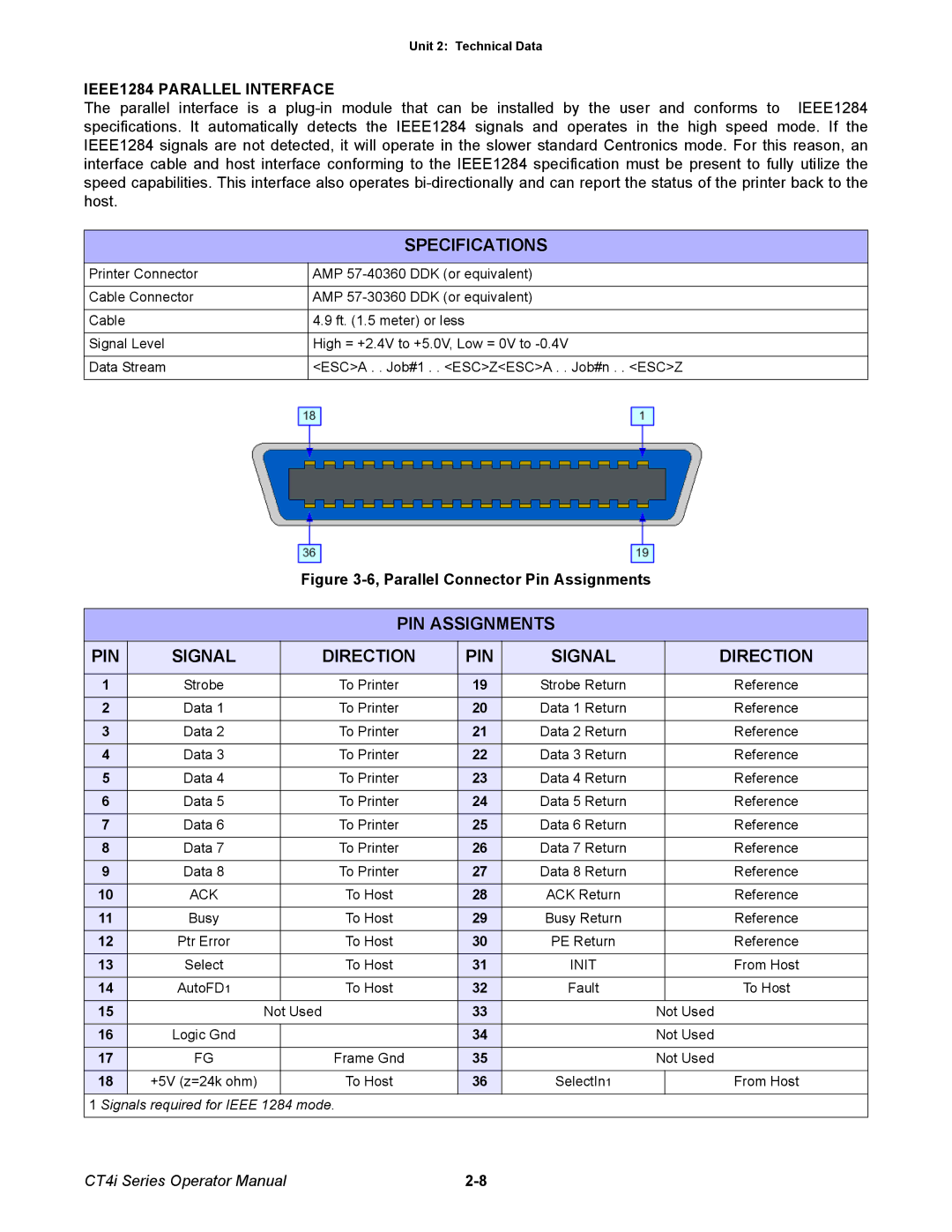
Figure 3-6, Parallel Connector Pin Assignments
PIN ASSIGNMENTS
PIN | SIGNAL |
| DIRECTION | PIN | SIGNAL |
| DIRECTION |
|
|
|
|
|
|
|
|
1 | Strobe |
| To Printer | 19 | Strobe Return |
| Reference |
2 | Data 1 |
| To Printer | 20 | Data 1 Return |
| Reference |
3 | Data 2 |
| To Printer | 21 | Data 2 Return |
| Reference |
4 | Data 3 |
| To Printer | 22 | Data 3 Return |
| Reference |
5 | Data 4 |
| To Printer | 23 | Data 4 Return |
| Reference |
6 | Data 5 |
| To Printer | 24 | Data 5 Return |
| Reference |
7 | Data 6 |
| To Printer | 25 | Data 6 Return |
| Reference |
8 | Data 7 |
| To Printer | 26 | Data 7 Return |
| Reference |
9 | Data 8 |
| To Printer | 27 | Data 8 Return |
| Reference |
10 | ACK |
| To Host | 28 | ACK Return |
| Reference |
11 | Busy |
| To Host | 29 | Busy Return |
| Reference |
12 | Ptr Error |
| To Host | 30 | PE Return |
| Reference |
13 | Select |
| To Host | 31 | INIT |
| From Host |
14 | AutoFD1 |
| To Host | 32 | Fault |
| To Host |
15 | Not Used |
| 33 |
| Not Used | ||
16 | Logic Gnd |
|
| 34 |
| Not Used | |
17 | FG |
| Frame Gnd | 35 |
| Not Used | |
18 | +5V (z=24k ohm) |
| To Host | 36 | SelectIn1 |
| From Host |
|
|
|
|
|
|
|
|
1 Signals required for IEEE 1284 mode.
CT4i Series Operator Manual |