174 CEV specifications
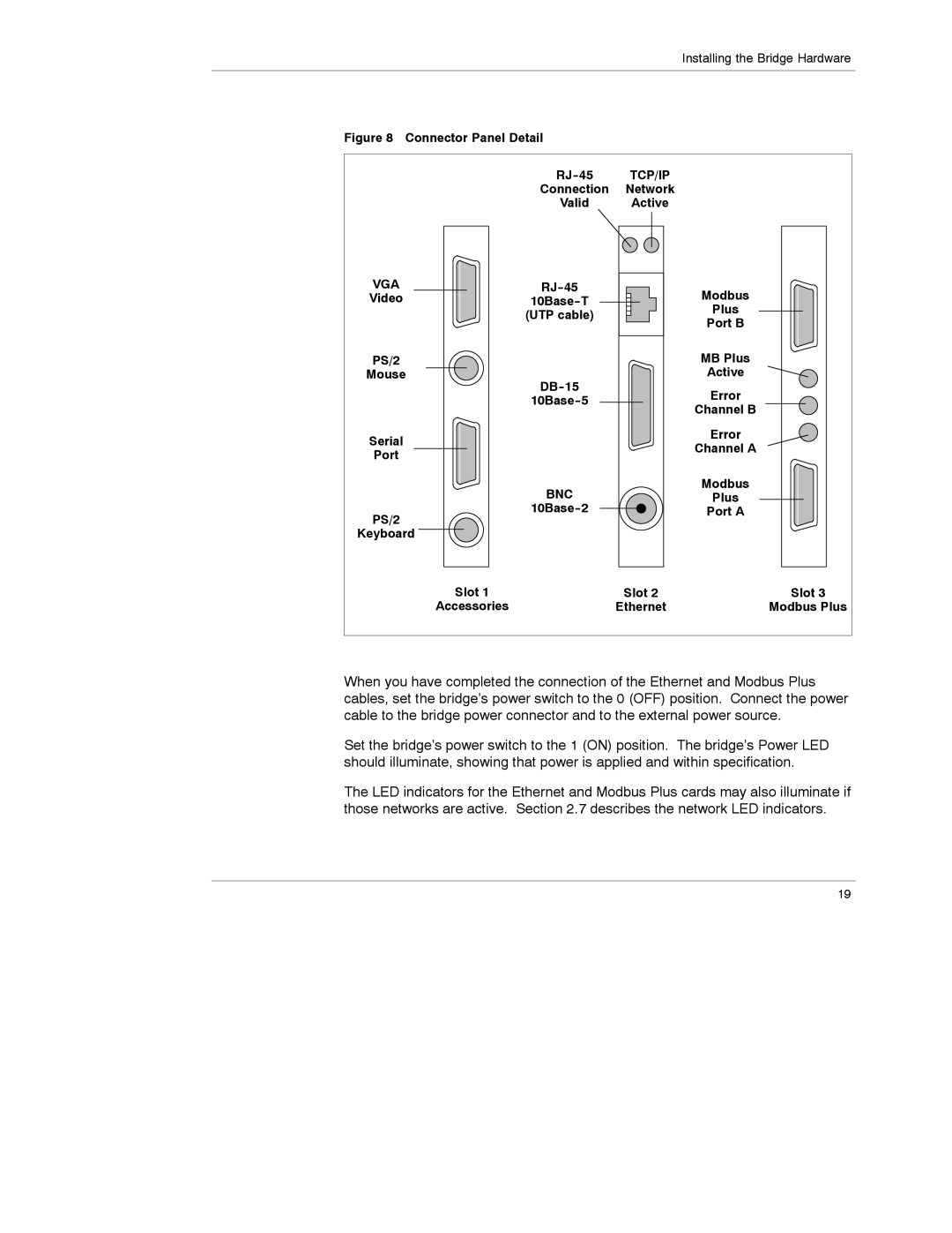
Schneider Electric, a global leader in energy management and automation, has designed the Schneider Electric 174 CEV to meet the evolving demands of industrial applications. This innovative controller is engineered to enhance efficiency, flexibility, and reliability across various sectors.One of the main features of the Schneider Electric 174 CEV is its robust communication capabilities. It supports multiple protocols, including Ethernet/IP, Modbus, and both serial and parallel communication interfaces. This multiplicity allows seamless integration with existing systems, ensuring that users can connect and manage devices within their operational setup without extensive changes to their infrastructure.
The 174 CEV is equipped with a powerful processing unit that ensures rapid data processing and real-time analytics. This is particularly advantageous for industries where quick decision-making is crucial. The controller is designed to handle large data sets and perform complex functions, all while maintaining optimal performance levels.
Another significant aspect of the Schneider Electric 174 CEV is its modular design. This feature allows for tailored solutions suited to specific application needs. Users can customize their setup by adding or removing modules based on their operational requirements, which enhances the controller’s versatility and longevity.
In terms of technology, the 174 CEV utilizes advanced algorithms for energy management and optimization. Users can benefit from predictive maintenance capabilities, which leverage data analytics to anticipate equipment failures before they occur. This proactive approach reduces downtime and maintenance costs, ultimately contributing to higher operational efficiency.
The controller also emphasizes user-friendly interfaces. With intuitive programming tools and a graphical user interface, operators can easily navigate through its functionalities, customize settings, and monitor performance metrics. This accessibility fosters greater user engagement and reduces the learning curve for new operators.
Safety is a top priority in the design of the Schneider Electric 174 CEV. The controller is built with compliance to international safety standards, ensuring that it can be deployed in a wide range of industries while guaranteeing the protection of both personnel and equipment.
Overall, the Schneider Electric 174 CEV stands out due to its combination of robust communication options, powerful processing capabilities, modular design, and user-friendly features. With its focus on energy efficiency and safety, the 174 CEV is an excellent choice for fulfilling the increasing demands of modern industrial environments.

