| PowerLogicTM Series EM4000 |
11/2013 | Installation Guide |
|
|
Connecting the Communications
Connections for communications using the Ethernet port or Modbus RTU port are described in this section.
Connecting the Ethernet Cable
If the Ethernet port is used to report data, an RJ45 patch cable is required to connect the Ethernet port to the local Ethernet network.
1. Route the cable through the slot in the PowerLogic EM4000 meter enclosure.
2. If the local network automatically assigns IP addresses through a DHCP server, the PowerLogic EM4000 meter will be able to report using its factory default IP settings. If the local network is configured for static IP addresses, refer to the PowerLogic EM4000 meter Configuration Guide for instructions on how to configure default static IP addresses.
Connecting the Modbus RTU Communications
If the Modbus port is used to report data, an RS422/RS485 serial cable is required to connect the Modbus RTU port to the local Modbus network.
1. Route the cable through the slot in the PowerLogic EM4000 meter enclosure.
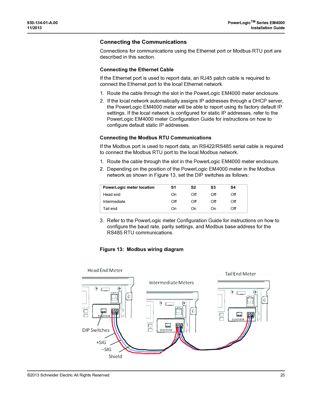
2. Depending on the position of the PowerLogic EM4000 meter in the Modbus network as shown in Figure 13, set the DIP switches as follows:
PowerLogic meter location | S1 | S2 | S3 | S4 |
Head end | On | Off | Off | Off |
Intermediate | Off | Off | Off | Off |
Tail end | On | On | On | Off |
|
|
|
|
|
3.Refer to the PowerLogic meter Configuration Guide for instructions on how to configure the baud rate, parity settings, and Modbus base address for the RS485 RTU communications.
Figure 13: Modbus wiring diagram
©2013 Schneider Electric All Rights Reserved | 25 |