Plug power cord into
IF YOU ARE NOT SURE THAT YOUR OUTLET IS
PROPERLY GROUNDED, HAVE IT CHECKED BY A QUALIFIED ELECTRICIAN.
WARNING: DO NOT PERMIT FINGERS TO TOUCH
THE TERMINALS OF PLUG WHEN INSTALLING OR
REMOVING THE PLUG TO OR FROM THE OUTLET.
WARNING: IF NOT PROPERLY GROUNDED THIS
POWER TOOL CAN INCUR THE POTENTIAL HAZARD
OF ELECTRICAL SHOCK, PARTICULARLY WHEN
USED IN DAMP LOCATIONS, IN PROXIMITY TO PLUMBING, OR OUT OF DOORS. IF AN ELECTRICAL SHOCK OCCURS THERE IS THE POTENTIAL OF A
SECONDARY HAZARD SUCH AS YOUR HANDS CONTACTING THE SAWBLAD E.
This saw is equipped with a
grounding type plug which has a grounding prong, approved by Underwriters' Laboratories and the Canadian Standards
Association. The ground Conductor has a green lug and is attached to the tool housing at one end and to the ground prong in the attachment plug at the other end.
This plug requires a mating
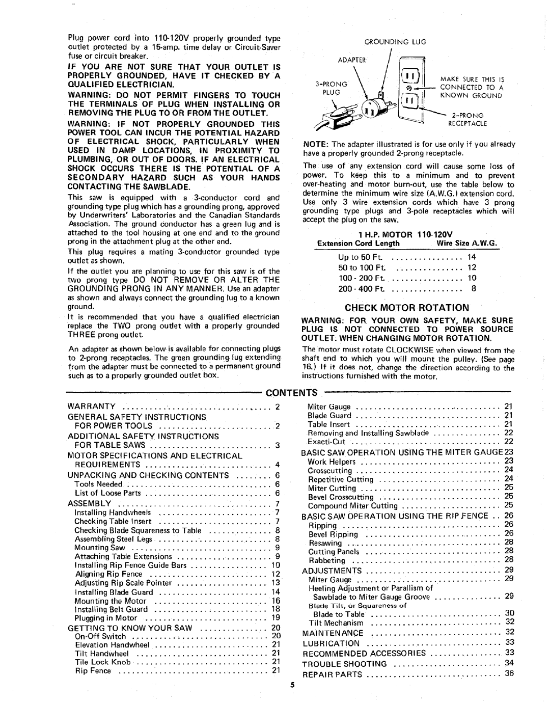
If the outlet you are planning to use for this saw is of the two prong type DO NOT REMOVE OR ALTER THE GROUNDING PRONG IN ANY MANNER. Use an adapter as shown and always connect the grounding lug to a known ground.
It is recommended that you have _ qualified electrician replace the TWO prong outlet with a ;)roperly grounded THREE prong outlet.
An adapter as shown below is available for connecting plugs to
| GROUNDING | LUG |
/ | CONNECTED TO A | |
|
| |
|
| RECEPTACLE |
NOTE: The adapter illustrated is for use only if you already have a properly grounded
The use of any extension cord will cause some loss of power. To keep this to a minimum and to prevent
| 1 H.P. MOTOR | ||
Extension Cord | Length | Wire Size A.W.G. | |
Upto | 50 Ft | 14 | |
50to | 100 Ft | 12 | |
100- | 200 | Ft | 10 |
200- | 400 | Ft | 8 |
CHECK MOTOR ROTATION
WARNING: FOR YOUR OWN SAFETY, MAKE SURE
PLUG IS NOT CONNECTED TO POWER SOURCE
OUTLET. WHEN CHANGING MOTOR ROTATION.
The motor must rotate CLOCKWISE when viewed from the shaft end to which you will mount the pulley. (See page
16.) If it does not, change the direction according to the
instructions furnished with the motor.
CONTENTS
WARRANTY |
|
| ................................. |
|
|
| 2 | |||
GENERAL |
| SAFETY | INSTRUCTIONS |
| ||||||
FOR POWER | TOOLS |
| 2 | |||||||
ADDITIONAL |
|
| SAFETY INSTRUCTIONS |
| ||||||
FOR | TABLE |
| SAWS | ........................... |
| 3 | ||||
MOTOR | SPECl FICATIONS | AND ELECTRICAL |
| |||||||
REQUIREMENTS |
| ............................ |
| 4 | ||||||
UNPACKING |
| AND CHECKING | CONTENTS | 6 | ||||||
Tools | Needed | ................................ |
|
|
| 6 | ||||
List | of | Loose | Parts | ............................ |
| 6 | ||||
ASSEMBLY |
| .................................. |
|
|
|
| 7 | |||
Installing |
| Handwheels | ......................... |
| 7 | |||||
Checking | Table | Insert |
| 7 | ||||||
Checking | Blade | Squareness | to | Table | 8 | |||||
Assembling | Steel | Legs |
| 8 | ||||||
Mounting | Saw | ............................... |
|
| 9 | |||||
Attaching | Table | Extensions | ..................... | 9 | ||||||
Installing |
| Rip | Fence | Guide | Bars | 10 | ||||
Aligning |
| Rip | Fence | .......................... |
| 12 | ||||
Adjusting | Rip | Scale | Pointer |
| ................... | 13 | ||||
Installing |
| Blade | Guard |
| 14 | |||||
Mounting | th_ | Motor | ......................... |
| 16 | |||||
Installing |
| Belt | Guard | ......................... |
| 18 | ||||
Plugging |
| in | Motor | ........................... |
| 19 | ||||
GETTING |
| TO |
| KNOW | YOUR | SAW | 20 | |||
Switch |
| .............................. |
|
| 20 | |||||
Elevation | Handwheel | ......................... |
| 21 | ||||||
Tilt | Handwheel |
| ............................. |
|
| 21 | ||||
Tile | Lock | Knob | ............................. |
|
| 21 | ||||
Rip | Fence | ................................. |
|
|
|
| 21 | |||
Miter |
| Gauge |
| 21 | |||
Blade |
| Guard |
| 21 | |||
Table |
|
| Insert |
| 21 | ||
Removing | and Installing | Sawblade | 22 | ||||
................................. |
| 22 | |||||
BASIC | SAW OPERATION | USING THE MITER GAUGE23 | |||||
Work |
| Helpers |
| 23 | |||
Crosscutting | ................................ |
| 24 | ||||
Repetitive | Cutting | ........................... | 24 | ||||
Miter |
| Cutting |
| 25 | |||
Bevel | Crosscutting | ........................... | 25 | ||||
Compound | Miter | Cutting | ...................... | 25 | |||
BASIC |
| SAW | OPERATION | USING THE RIP£ENCE | . . 26 | ||
Ripping |
| ................................... |
| 26 | |||
Bevel |
| Ripping | ............................. | 26 | |||
Resawing | .................................. |
| 28 | ||||
Cutting | Panels |
| 28 | ||||
Rabbeting | ................................. |
| 28 | ||||
ADJUSTMENTS |
| 29 | |||||
Miter |
|
| Gauge |
| 29 | ||
Heeling | Adjustment | or Parallism of |
| ||||
Sawblade | to Miter Gauge Groove | 29 | |||||
Blade Tilt, or Squareness of |
| ||||||
Blade | to | Table | ............................. | 30 | |||
Tilt | Mechanism | ............................. | 32 | ||||
MAINTENANCE | ............................. | 32 | |||||
LUBRICATION |
| 33 | |||||
RECOMMENDED | ACCESSORIES | 33 | |||||
TROUBLE | SHOOTING | 34 | |||||
REPAI |
| R PARTS |
| 36 | |||