LC-30HV2M
Contents
LC-30HV2M
Important Safety Precautions
Dear Sharp customer
Important Safety Precautions
Precautions when transporting the display
Supplied accessories
Removing the terminal cover
Setting the system
Preparation
AVC System rear view
How to route the system cable
Preparation
Using the remote control unit
Inserting the batteries
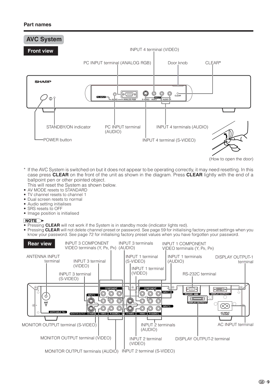
Part names
Display
AVC System
Part names
Remote control unit
Watching TV
Connecting to an antenna
Connecting to the power outlet
Basic connection
Using Headphones
Watching TV
Turning on the power
Turning off the power
Initial auto installation
Using 0 9 on the remote control unit
Using Flashback a on the remote control unit
Using CHa/bon the remote control unit
Simple button operations for changing channels
Display VOLl/k Volume adjustment Mute
Simple button operation for changing volume/sound
Using e on the remote control unit
Audio status
Watching TV Using h on the remote control unit
SRS sound options
When receiving a bilingual signal
Watching TV Using Sound on the remote control unit
Nicam TV broadcasts When receiving a stereo signal
When receiving a monaural signal
List of AV menu items to help you with operations
Basic adjustment settings
AV Input mode menu items
First Menu
Basic adjustment settings
PC Input mode menu items
List of PC menu items to help you with operations
Language setting
Auto installation
Programme auto search
Auto sorting
Auto labelling
Automatically sorts TV channels
Programme setup
Auto search
Do not shut down the System until Sorts channels. displays
Additional channels entry
Manual setting for each channel
Programme Setup Manual menu
Then press Enter
Selecting Store displays the following
Search tuning
Press a/bto select Search and then press
Colour system menu
Fine tuning menu
Fine tuning
Colour system
Labelling menu
Sound menu
Sound system
Labelling channels
Press a/bto set Lock to On, and then press
Setting the child lock
Press a/bto select Lock, and then press
Lock menu
Sort menus
Basic adjustment settings Sort
Press b
Language setting
Press a/bto select Language, and then press
Teletext Language Setting
Press Menu Press a/bto select Text Lang., and then press
Adjustments items for AV source
Picture adjustments
Adjustments items for PC source
Press a/bto select Advanced, and then press
Colour temperature
Film mode
Press a/bto select Colour Temp, and then press
Press a/bto select Black, and then press
Black
Monochrome
Press a/bto select Monochrome, and then press
For viewing a more beautiful high quality picture
Setting
Press a/bto select I/P Setting, and then press
Press Menu Press a/bto select Picture, and then press
Press a/bto select Cool Climate, and then press
Cool Climate
Vivid Colour
Press a/bto select Vivid Colour, and then press
Bass
Sound adjustment
Balance
Power save
Power control
Power control for AV source
No signal off
No operation off
Selected item Description Off
Power control for PC source
Power management
Mode1
Using external equipment
Watching a DVD image
Using external equipment
Connecting a DVD player
Displaying a DVD image
Watching a VCR image
Connecting a VCR
Displaying a VCR image
Displaying broadcasts via an Hdtv tuner
Connecting an Hdtv tuner
Watching broadcasts via an Hdtv tuner
Hdtv tuner
Displaying an image of the game player or camcorder
Connecting a game player or camcorder
Enjoying a game player or viewing camcorder images
AVC System front view
Displaying an image from a computer
Connecting a computer
Viewing an image from a computer
Use the PC terminals to connect a computer
Removing the speakers This unit has detachable type speakers
Before attaching/detaching speakers
Press a/bto select Position, and then press
Useful adjustment settings
Image position AV Input mode only
Description
Useful adjustment settings
Moving the picture on the screen
Press a/bto select Auto Sync., and then press
Auto Sync. adjustment PC Input mode only
Fine Sync. adjustment PC Input mode only
Press a/bto select Fine Sync., and then press
Input 1 signal menu
Input signal source
Input signal setting
Input 3 signal menu
Mode selection for the TV, Input 1 to 4 terminals
Colour system setting AV Input mode only
AV mode
Mode selection for the PC terminal
Manual Selection
Wide mode AV Input mode
Auto Selection
Below are examples of input signals and the image displayed
Wide mode PC Input mode
Wide Mode display
Normal Full Dot by Dot
Picture aspect ratio AV Input mode only
Wide screen signalling WSS AV Input mode only
WSS signal 43 screen Mode Normal
Full mode Mode2
Selecting Full Mode display AV Input mode only
Full Mode screen Full mode Mode1
Press a/bto select Full Mode, and then press
Press a/bto select Audio Out, and then press
Sleep timer
Audio out
120
Press a/bto select Password, and then press
Password setting for child lock AV Input mode only
Clearing the password
Enter your 4-digit password with 0 9, and then press Enter
Dual screen functions
Useful features
Dual screen
Update the still image by pressing Enter
Useful features Picture and still image
Press d to exit still image
Page
Displaying Subpages
Useful features
Displaying TOP Overview
Teletext. Follow the steps below to display the time
Time display
You can display the time information included
Select a TV channel providing Teletext information
Appendix
Troubleshooting
Problem Possible Solution
Use in hot and cold rooms locations
Resolution Frequency Remarks
Computer compatibility chart
Appendix
Computer Control of the System
RS-232C port specifications
Command format
Communication conditions
Command table
Response code format
Specifications
30oLCD Colour TV, Model LC-30HV2M
Dimensional drawings
Display
Dimensional drawings
HOW to SET the Factory Presets
Sharp Corporation