RJ-45 Pin Numbering
End 1 | End 2 | ||
|
|
|
|
1 | (TD+) | 1 | (TD+) |
|
|
|
|
2 | 2 | ||
|
|
|
|
3 | (RD+) | 3 | (RD+) |
|
|
|
|
6 | 6 | ||
|
|
|
|
Pins 4, 5, 7 and 8 are not connected.
Crossover Cable
End 1 | End 2 | ||
|
|
|
|
1 | (TD+) | 3 | (RD+) |
|
|
|
|
2 | 6 | ||
|
|
|
|
3 | (RD+) | 1 | (TD+) |
|
|
|
|
6 | 2 | ||
|
|
|
|
Pins 4, 5, 7 and 8 are not connected.
Table
RJ-45 Pin Assignments
All LAN ports on the SpeedStream 2614 support automatic
Pin | MDI Signal Name* |
|
1 | Transmit Data (TD+) | Receive Data (RD+) |
|
|
|
2 | Transmit Data | Receive Data |
|
|
|
3 | Receive Data (RD+) | Transmit Data (TD+) |
|
|
|
6 | Receive Data | Transmit Data |
|
|
|
Pins 4, 5, 7 and 8 are not connected.
* The “+” and
Table
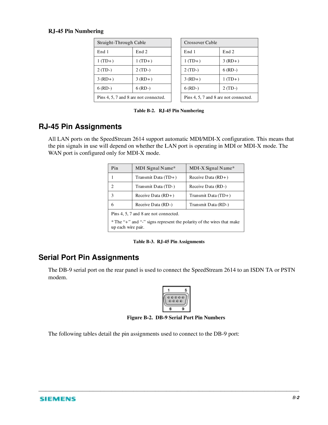
Serial Port Pin Assignments
The
Figure B-2. DB-9 Serial Port Pin Numbers
The following tables detail the pin assignments used to connect to the