Jaguar Model |
| 37 | |||
IV. CHECK COMBUSTION AND FUEL INPUT RATE | 2. If the CO2 is not 0.2% at the low firing rate, then the |
| |||
A. Start and run the burner at the high firing rate, by using the |
| gas valve needs to be accessed for proper adjust- | |||
| ment. Remove the boiler jacket top cover, 3 front | ||||
“System Test” mode in the “View and changing system |
| ||||
| cover panels, and enclosure front cover (see figure 2 | ||||
setting” menu. Refer to Table 5 on page 33. |
| ||||
| on page 3 for locations. | ||||
|
|
| |||
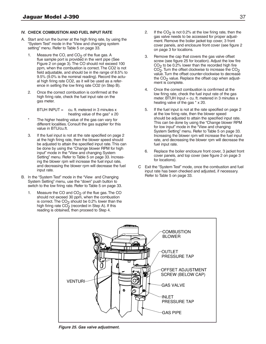
1. | Measure the CO, and CO2 of the flue gas. A | 3. Remove the cap that covers the gas valve offset | |||
| flue sample port is provided in the vent pipe (See |
| screw (see figure 25 for location). Adjust the low fire | ||
| Figure 2 on page 3). The CO should not exceed 100 |
| |||
|
| CO2 to be 0.2% lower than the recorded high fire | |||
| ppm, when the combustion is correct. The CO2 is not |
| |||
|
| CO2. Turn the offset clockwise to increase the CO2 | |||
| field adjustable, and should be in the range of 8.5% to |
| |||
|
| value. Turn the offset | |||
| 9.5% (9.0% is the nominal reading). Record the actu- |
| |||
|
| the CO2 value. Replace the offset cap when adjust- | |||
| al high firing rate CO2, as it will be used as a refer- |
| |||
|
| ment is complete. | |||
| ence in setting the low firing rate CO2 (in Step B). |
| |||
| 4. | Once the correct combustion is confirmed at the | |||
2. | Once the correct combustion is confirmed at the | ||||
| low firing rate, check the fuel input rate of the gas | ||||
| high firing rate, check the fuel input rate on the |
| |||
|
| meter. BTUH Input = cu. ft. metered in 3 minutes x | |||
| gas meter. |
| |||
|
| heating valve of the gas * x 20. | |||
|
|
| |||
| BTUH INPUT = cu. ft. metered in 3 minutes x | 5. If the fuel input is not at the rate specified on page 2 | |||
| heating value of the gas* x 20 |
| at the low firing rate, then the blower speed | ||
* | The higher heating value of the gas can vary for |
| should be adjusted to attain the specified input rate. | ||
| This can be done by using the “Change blower RPM | ||||
| different localities. Consult the gas supplier for this |
| |||
|
| for low input” mode in the “View and changing | |||
| value in BTU/cu.ft. |
| |||
|
| System Setting” menu. Refer to Table 5 on page 33. | |||
3. | If the fuel input is not at the rate specified on page 2 |
| |||
| Increasing the blower rpm will increase the fuel input | ||||
| at the high firing rate, then the blower speed should |
| rate, and decreasing the blower rpm will decrease the | ||
| be adjusted to attain the specified input rate. This can |
| fuel input rate. | ||
| be done by using the “Change blower RPM for high | 6. | Replace the boiler enclosure front cover, 3 jacket front | ||
| input” mode in the “View and changing System | ||||
|
| cover panels, and top cover (see figure 2 on page 3 | |||
| Setting” menu. Refer to Table 5 on page 33. Increas- |
| |||
|
| for locations). | |||
| ing the blower rpm will increase the fuel input rate, |
| |||
|
|
|
| ||
| and decreasing the blower rpm will decrease the fuel | C Exit the “System Test” mode, once the combustion and fuel | |||
| input rate. | input rate has been checked and adjusted, if necessary. | |||
B. In the “System Test” mode in the “View and Changing | Refer to Table 5 on page 33. |
| |
System Setting” menu, use the “down” push button to |
|
switch to the low firing rate. Refer to Table 5 on page 33. |
|
1.Measure the CO and CO2 of the flue gas. The CO should not exceed 30 ppm, when the combustion
is correct. The CO2 should be 0.2% lower than the high firing rate CO2 (recorded in Step A). If this reading is obtained, then proceed to Step 4.
COMBUSTION |
BLOWER |
OUTLET |
PRESSURE TAP |
OFFSET ADJUSTMENT |
SCREW (BELOW CAP) |
VENTURI |
GAS VALVE |
INLET |
PRESSURE TAP |
GAS PIPE |