Jaguar Model | 7 |
The vent connector on the boiler is designed to directly accom- modate either PVC/CPVC Schedule 40 pipe or the listed stain- less steel vent systems by utilizing an adapter. The adapter has a
Make sure the pipes are round and
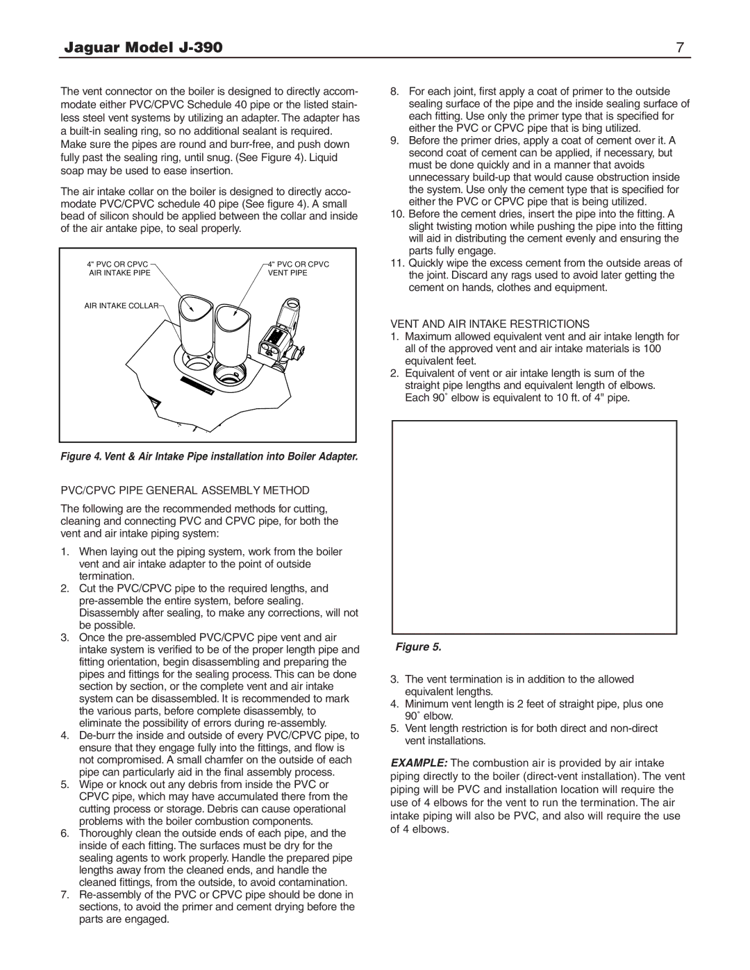
The air intake collar on the boiler is designed to directly acco- modate PVC/CPVC schedule 40 pipe (See figure 4). A small bead of silicon should be applied between the collar and inside of the air antake pipe, to seal properly.
4" PVC OR CPVC | 4" PVC OR CPVC |
AIR INTAKE PIPE | VENT PIPE |
AIR INTAKE COLLAR |
|
8.For each joint, first apply a coat of primer to the outside sealing surface of the pipe and the inside sealing surface of each fitting. Use only the primer type that is specified for either the PVC or CPVC pipe that is bing utilized.
9.Before the primer dries, apply a coat of cement over it. A second coat of cement can be applied, if necessary, but must be done quickly and in a manner that avoids unnecessary
10.Before the cement dries, insert the pipe into the fitting. A slight twisting motion while pushing the pipe into the fitting will aid in distributing the cement evenly and ensuring the parts fully engage.
11.Quickly wipe the excess cement from the outside areas of the joint. Discard any rags used to avoid later getting the cement on hands, clothes and equipment.
VENT AND AIR INTAKE RESTRICTIONS
1.Maximum allowed equivalent vent and air intake length for all of the approved vent and air intake materials is 100 equivalent feet.
2.Equivalent of vent or air intake length is sum of the straight pipe lengths and equivalent length of elbows. Each 90˚ elbow is equivalent to 10 ft. of 4" pipe.
Figure 4. Vent & Air Intake Pipe installation into Boiler Adapter.
PVC/CPVC PIPE GENERAL ASSEMBLY METHOD
The following are the recommended methods for cutting, cleaning and connecting PVC and CPVC pipe, for both the vent and air intake piping system:
1.When laying out the piping system, work from the boiler vent and air intake adapter to the point of outside termination.
2.Cut the PVC/CPVC pipe to the required lengths, and
3.Once the
4.
5.Wipe or knock out any debris from inside the PVC or CPVC pipe, which may have accumulated there from the cutting process or storage. Debris can cause operational problems with the boiler combustion components.
6.Thoroughly clean the outside ends of each pipe, and the inside of each fitting. The surfaces must be dry for the sealing agents to work properly. Handle the prepared pipe lengths away from the cleaned ends, and handle the cleaned fittings, from the outside, to avoid contamination.
7.
Figure 5.
3.The vent termination is in addition to the allowed equivalent lengths.
4.Minimum vent length is 2 feet of straight pipe, plus one 90˚ elbow.
5.Vent length restriction is for both direct and
EXAMPLE: The combustion air is provided by air intake piping directly to the boiler