6 | Jaguar Model |
For both direct and
- Openings must never be reduced or closed. If doors or win- dows are used for air supply, they must be locked open.
-Protect against closure of openings by snow and debris. Inspect frequently.
-No mechanical draft exhaust or supply fans are to be used in or near the boiler area.
-Boiler area must never be under negative pressure. The flow of combustion and ventilating air to the boiler must not be obstructed.
FLUE GAS VENTING REQUIREMENTS
The Jaguar
THE FOLLOWING INSTRUCTIONS MUST BE CAREFULLY READ AND FOLLOWED IN ORDER TO AVOID ANY HAZ- ARDOUS CONDITIONS DUE TO IMPROPER INSTALLATION OF THE AIR INTAKE AND FLUE GAS VENTING SYSTEM.
The vent piping installation MUST be in accordance with these instructions and with ANSI
The use of a vent damper is NOT permitted on this boiler series.
ADDITIONAL REQUIREMENTS FOR THE COMMONWEALTH OF MASSACHUSETTS
When the Bobcat is installed and used in the Commonwealth of Massa- chusetts, the following additional requirements pursuant to Massachusetts code 248 CMR MUST be met:
(1). Exisiting chimneys shall be permitted to have their use continued when a gas conversion burner is installed, and shall be equipped with a manual reset device that will automatically shut off gas to the burner in the event of a sustained
(2)(a). For all side wall horizontally vented gas fueld equipment installed in every dwelling, building or structure used in whole or part for residential purposes, including those owned or operated by the Commonwealth and where the side wall exhaust vent termination is less than seven (7) feet above finsihed grade in the area of the venting, including but not limited to decks and porches, the following requirements shall be satisfied:
1.INSTALLATION OF CARBON MONOXIDE DETECTORS. At the time of installation of the side wall horizontal vented fueled equipment, the installing plumber or gasfitter shall observe that a hard wired carbon monoxide detector with an alarm and battery
a.In the event that the side wall horizontally vented gas fueld equipment is installed in a crawl space or an attic, the hard wired carbon monoxide detector with alarm and battery back up may be installed on the next adja- cent floor level.
b.In th event that the requirements of this subdivision can not be met at the time of completion of installation, the owner shall have a period of thir- ty (30) days to comply with the above requirements; provided, however, that during said thirty (30) day period, a battery operated carbon monoxide detector with an alarm shall be installed.
2.APPROVED CARBON MONOXIDE DETECTORS. Each carbon
monoxide detector as required in accordance with the above provisions shall comply with NFPA 720 and be ANSI/UL 2034 listed and IAS certified.
3.SIGNAGE. A metal or plastic identification plate shall be permanently mounted to the exterior of the building at a minimum height of eight (8) feet above grade directly in line with the exhaust vent terminal for the hori- zontally vented gas fueled heating appliance or equipment. The sign shall read, in print size no less that
DIRECTLY BELOW, KEEP CLEAR OF ALL OBSTRUCTIONS”.
4.INSPECTION. The state or local gas inspector of the side wall horizon- tally vented gas fueled equipment shall not approve the installation unless, upon inspection, the inspector observes carbon monoxide detectors and signage installed in accordance with the provisions of 248 CMR 5.08(2)(a)1 through 4.
(b)EXEMPTIONS. The following equipment is exempt from 248 CMR 5.08(2)(a)1 through 4:
1.The equipment listed in Chapter 10 entitled “Equipment Not Required TO Be Vented” in the most current edition of NFPA 54 as adopted by the Board; and
2.Product Approved side wall horizontally vented gas fueled equip- ment installed in a room or structure separate from the dwelling, build- ing or structure used in whole or part for residential purposes.
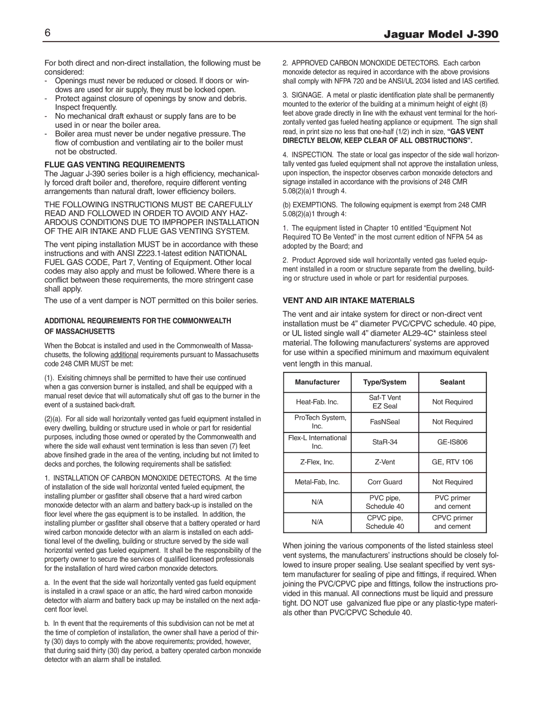
VENT AND AIR INTAKE MATERIALS
The vent and air intake system for direct or
vent length in this manual.
Manufacturer | Type/System | Sealant | |
|
|
| |
Not Required | |||
EZ Seal | |||
|
| ||
|
|
| |
ProTech System, | FasNSeal | Not Required | |
Inc. | |||
|
| ||
|
|
| |
Inc. | |||
|
| ||
|
|
| |
GE, RTV 106 | |||
|
|
| |
Corr Guard | Not Required | ||
|
|
| |
N/A | PVC pipe, | PVC primer | |
Schedule 40 | and cement | ||
| |||
|
|
| |
N/A | CPVC pipe, | CPVC primer | |
Schedule 40 | and cement | ||
| |||
|
|
|
When joining the various components of the listed stainless steel vent systems, the manufacturers’ instructions should be closely fol- lowed to insure proper sealing. Use sealant specified by vent sys- tem manufacturer for sealing of pipe and fittings, if required. When joining the PVC/CPVC pipe and fittings, follow the instructions pro- vided in this manual. All connections must be liquid and pressure tight. DO NOT use galvanized flue pipe or any