CONSOLE PORT PIN ASSIGNMENTS

Console Port Pin Assignments

The DB-9 serial port on the switch’s front panel is used to connect to the switch for out-of-band console configuration. The on-board menu-driven configuration program can be accessed from a terminal or a PC running a terminal emulation program. The pin assignments used to connect to the serial port are provided in the following tables.

1 5

69

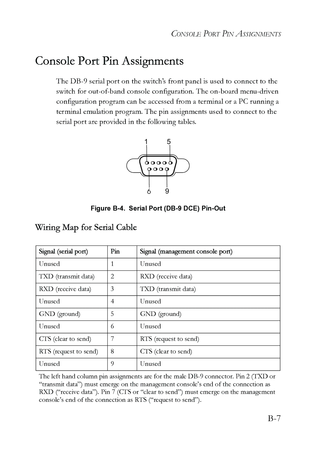
Figure B-4. Serial Port (DB-9 DCE) Pin-Out

Wiring Map for Serial Cable

Signal (serial port)

Pin

Signal (management console port)


Unused

1

Unused


TXD (transmit data)

2

RXD (receive data)


RXD (receive data)

3

TXD (transmit data)


Unused

4

Unused


GND (ground)

5

GND (ground)


Unused

6

Unused


CTS (clear to send)

7

RTS (request to send)


RTS (request to send)

8

CTS (clear to send)


Unused

9

Unused


The left hand column pin assignments are for the male DB-9 connector. Pin 2 (TXD or “transmit data”) must emerge on the management console’s end of the connection as RXD (“receive data”). Pin 7 (CTS or “clear to send”) must emerge on the management console’s end of the connection as RTS (“request to send”).

B-7

Page 61
Image 61
SMC Networks SMC6724L3 INT manual Console Port Pin Assignments, Wiring Map for Serial Cable