DFS-700 DFS-700P
Table of Contents
Self-diagnosis
DFS-700/700P
Page
Manual Structure
Page
Operating Instructions
DFS-700/700P
Table of Contents
Inserting Characters and Graphics
Table of Contents
Inserting Characters and Graphics 1 Title Key
Freezing an Input Image Frame Memory
Advanced special effects
Features of This System
Support for wide range of input/output signal formats
Comprehensive title key functions
Features of This System
Option Boards
Control Panel
Numbers shown in parenthesis for more details
Delegation section
Control Panel
Primary cross-point bus section
Effect transition section
Pattern/numeric keypad
Fade-to-black and DSK section
Editor and GPI buttons
Menu control section
LUM luminance button Press this to display a
SET UP button
DSK downstream keyer section
Edge section
User program section
Effect control section
Snapshot section
Front Panel
Qs 25-pin connector rear panel
Processor Unit
Rear Panel
SDI Input 1 to 4, Option 5 to 8 BNC-type
Processor Unit
COMPONENT/COMPOSITE Option 5 to 8 BNC-type
Video Option 5 to 8 4-pin
Basic operations to be
DME Switcher Introduction
Sequence of Operations
Always carried out Carried out as required
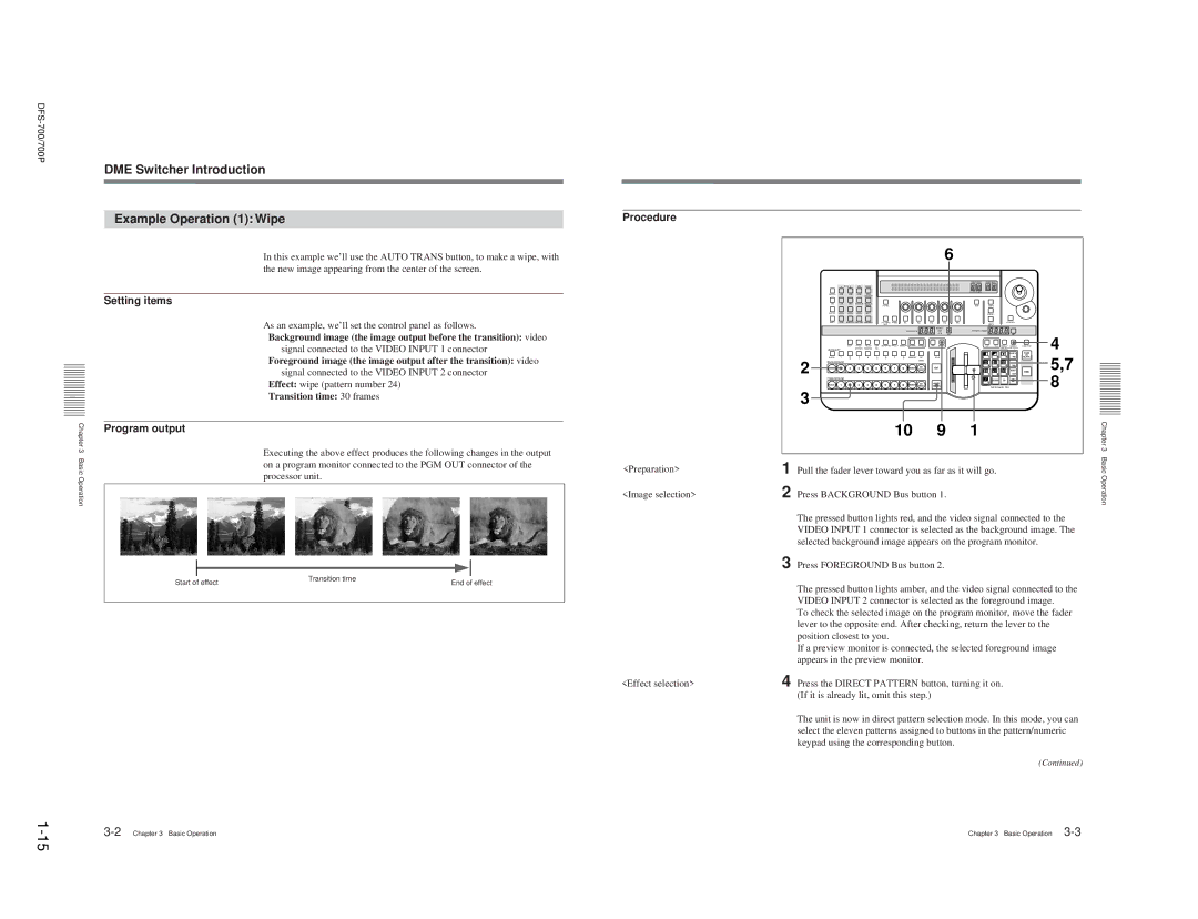
Procedure
DME Switcher Introduction Example Operation 1 Wipe
Setting items
Program output
Example Operation 2 Picture-in-Picture
DME Switcher Introduction
Border on
Both the Background bus INT Video button
Move the fader lever to the opposite end
Foreground bus button 1 light red
To start the demonstration
DME Switcher Introduction Demonstration
To end the demonstration
Demonstration with user-registered snapshots
Changing settings
DME Switcher Introduction Using the Menus
Accessing a menu
To change the menu
Background Image and Foreground Image
20Selecting Images
Selecting the background image and foreground image
Selecting Images
Previewing the image after an effect is executed
Transition effects and animation effects
Selecting an Effect
Types of Effect
Modifications to effects
Background image to the left
Selecting an Effect Example Effects
Foreground image appears from the right, and slides over
Foreground fills the screen
Nonlinear effects
Selecting an Effect
Two-channel DME effects
Selection in Direct Pattern Selection Mode
3D mapping effects
If you enter a wrong number
Adjusting the number before confirming
Press the SET button, turning it on
To blur the image boundary
When effect parameters are already adjusted
Beveled Edge, and Crop
To remove unwanted portions of the image
Changing the Pattern Position and Size Location XYZ
Indications in the Edge menu with square brackets
Modifying the Pattern User Modifiable Effects
Procedure
Using knobs and buttons F1 to F5, set the parameters
Changing the Pattern Position and Size Location XYZ
Luminance Key
Inserting Characters and Graphics 1 Title Key
Modifying the Pattern User Modifiable Effects
Example of user modifiable effect parameters
Necessary
Inserting Characters and Graphics 1 Title Key
To remove the luminance key
Manual chroma keying
Auto chroma keying
Auto chroma keying
Two-channel chroma keying
Menu changes to the auto chroma key menu T1ACR
Making fine adjustments to the composite image
Cursor adjustment Control knob
If there are variations in the background color
Manual chroma key
Use the same procedure as for an auto chroma key see
34Inserting Characters and Graphics 1 Title Key
Parameter to on
Angle setting Example using a blue background color
Adjusting the hue range for chroma keying the angle setting
Watching the composite image on the program monitor, turn
Removing the mask
Mask menu, press the F5INVERT button, setting it to on
Inserting Characters and Graphics 2 Downstream Key
Press the Mask button lit in , turning it off
Inserting Characters and Graphics 2 Downstream Key
Applying a border to a downstream key
To invert the downstream key source signal
To remove the border
To set the transition time, use the following procedure
Setting Up a Transition
Setting the Transition Time
To mask a part of the downstream key
Operation of transition effects
Setting Up a Transition
Setting the Transition Direction
Operation of animation effects
Using the fader lever and Auto Trans button together
Using the Auto Trans button
Using the fader lever
Executing an Effect
Adjusting Color Mattes
Executing an Effect
Adjusting Color Mattes
Adjusting Image Colors Color Correction
To copy a matte color
Freezing an Input Image Frame Memory Function
Adjusting Image Colors Color Correction
F5Gamma adjust the gamma value of the luminance signal
F4HueRot set the hue
Fade-to-Black
Freezing an Input Image Frame Memory Function
To change the direct pattern assignment
Changing Direct Pattern Assignments
Press the SET button
Changing Direct Pattern Assignments
User Program Effects
Constructing a User Program Effect
Modification Parameters
User Program Effects Types of User Program Effect
Effect type Pattern number
User Program Effects
Displaying parameter values
Resetting the parameters to their initial values
Setting the type of interpolation
About the key frame duration
Sequence of key frame maximum eight
User Program Effects Creating New User Program Effects
Button once more
To change the key frame parameters
User Program Effects Editing User Program Effects
To recall a user program effect
User program effect
Adding a key frame
Deleting a key frame
To save key frame data
Copying a key frame
To recall a key frame
With buttons 0 to 9 and press Enter
User Program Effects Executing User Program Effects
Deleting All User Program Effects
Effect
Snapshots
To cancel the snapshot saving operation
Saving a Snapshot
Snapshots Recalling a Snapshot
Snapshot Demonstration
Control From the PVE-500
Control using PVE-500 control signals
Downstream key control using GPI signals
Snapshots Reinitializing the Snapshots
Roll Editing
Signal flow
Control From the PVE-500 Preparations
Cut Editing
Control From the PVE-500
Control From the BVE-600
On the BVE-600
Timing of the trigger T1/T2 signals
Control From the BVE-600 Roll Editing
Connectable editing control units
Control using editor control signals
Control From the BVE-900/2000 Series
On the BKE-900/910
Control From the BVE-900/2000 Series
Control Using GPI Signals
Editing point delay
Executing effects in the reverse direction
Flow of signals in A/B roll editing is as follows
Control Using GPI Signals
Timing of the GPI signal
Turning a Downstream Key On and Off
Preparations on the DFS-700/700P
Settings for preread editing
Preread Editing
Preparations on a BVE-2000 earlier than Ver
Key Signal Connections
66Basic System Connections
System Connections for Preread Editing
When using GPI signals
Connections for an A/B Roll Editing System
System Setup page 1/8
Setup Menu Settings
Setup Menu Organization
When using the BVE-2000
Setup Menu Settings System Information Display page 2/8
Input Video Setup page 3/8
Output Video Setup page 4/8
Primary inputs and signal formats
Loading User Settings From Memory page 7/8
70Setup Menu Settings Control Panel Setup page 5/8
Initializing User Settings page 6/8
Saving User Settings in Memory page 8/8
Following warning messages are displayed
Configuration Installed
Effect Type List
Display
Effect Type List
Effect Control Parameter List
F6 to F10 Menu
Effect Control Parameter List
BTML/BOTTOM/BTMR
LINE1/LINE2/PIXEL1/P1XEL2
BOTTOM/HORZ/VERT
2700 3D page turn 2701 F1 Direction of turn Angle = 0 to
14Appendixes
16Appendixes
18Appendixes
Effect Motion Types
Direction type Characteristics
Pattern No
Trail Trail
Lighting Lighting
Option Options
Effect Pattern Variant Forms and Decorations
Edge Crop Locate Lighting Trail Option
711
711 712
Effect Pattern Image List
FG FG
Effect Pattern Image List
1021 1023 1025 1027
Appendixes Spotlight
DFS-700/700P
38Appendixes Appendixes A-39
BG FG FG FG FG BG
Album turn 1850 1852 1851 1853 Flip, Tumble
2201 2203 2210
Effect Pattern Image List
48Appendixes Appendixes A-49
Effect Pattern Image List
52Appendixes Appendixes A-53
2ch picture-in-picture 2500 2501 2520
Split page turn 2560
Effect Pattern Image List
100Effect Pattern Image List
To Exchange the Button Labels
Effect Pattern Image List
SpecifiSpecificationsations
GlossaryGlossary
Index
105
Index
106