SECTION 4
TEST MODE
*Note:
As this unit has only a few buttons, one button is assigned with several functions in the test mode.”
Press the z button, AMS knob to switch the functions.
• | Each time the z button is pressed, the display switches in the follwing order, “PGM” t “blank” t “PGM” t | |||
• | Rotate the | AMS | knob and the display switches in the following order, “blank” t “TOC” t “EDIT” t “TOC EDIT” t | |
| “[ | ]” t “[TOC ]” t “[ EDIT]” t “[TOC EDIT]” t “blank” t – | ||
For simplicity, operations of
z
button will not be discribed here.
Example)
x/Z :
x/Z “PGM” : Display “PGM” and press the x/Z button.
The functions of each button change with the display.
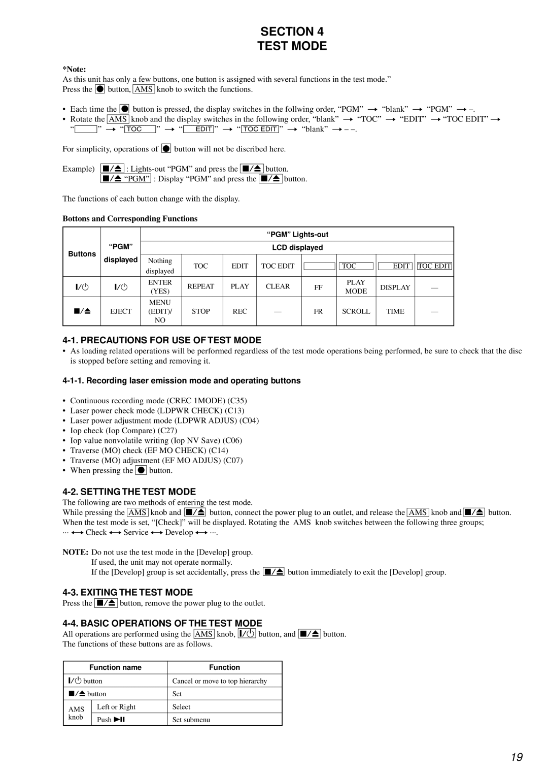
Bottons and Corresponding Functions
|
|
|
|
| “PGM” |
|
|
|
|
|
|
|
| |||
| “PGM” |
|
|
|
|
|
|
|
|
|
|
|
|
|
|
|
Buttons |
|
|
| LCD displayed |
|
|
|
|
|
|
|
| ||||
displayed |
|
|
|
|
|
|
|
|
|
|
|
|
|
|
| |
Nothing |
|
|
|
|
|
|
|
|
|
|
|
|
|
| ||
|
|
|
|
|
|
|
|
|
|
|
|
|
|
| ||
|
| displayed | TOC | EDIT | TOC EDIT |
|
|
| TOC |
|
| EDIT |
|
| TOC EDIT |
|
|
|
|
|
|
|
|
|
|
|
|
|
|
|
|
| |
|
|
|
|
|
|
|
|
|
|
|
|
|
|
|
|
|
@/1 | @/1 | ENTER | REPEAT | PLAY | CLEAR |
| FF |
| PLAY |
|
| DISPLAY |
|
| — | |
(YES) |
|
| MODE |
|
|
|
| |||||||||
|
|
|
|
|
|
|
|
|
|
|
|
|
|
| ||
|
|
|
|
|
|
|
|
|
|
|
|
|
|
|
|
|
|
| MENU |
|
|
|
|
|
|
|
|
|
|
|
|
|
|
x/Z | EJECT | (EDIT)/ | STOP | REC | — |
| FR |
| SCROLL |
|
| TIME |
|
| — | |
|
| NO |
|
|
|
|
|
|
|
|
|
|
|
|
|
|
|
|
|
|
|
|
|
|
|
|
|
|
|
|
|
|
|
4-1. PRECAUTIONS FOR USE OF TEST MODE
•As loading related operations will be performed regardless of the test mode operations being performed, be sure to check that the disc is stopped before setting and removing it.
4-1-1. Recording laser emission mode and operating buttons
•Continuous recording mode (CREC 1MODE) (C35)
•Laser power check mode (LDPWR CHECK) (C13)
•Laser power adjustment mode (LDPWR ADJUS) (C04)
•Iop check (Iop Compare) (C27)
•Iop value nonvolatile writing (Iop NV Save) (C06)
•Traverse (MO) check (EF MO CHECK) (C14)
•Traverse (MO) adjustment (EF MO ADJUS) (C07)
•When pressing the z button.
4-2. SETTING THE TEST MODE
The following are two methods of entering the test mode.
While pressing the AMS knob and x/Z button, connect the power plug to an outlet, and release the AMS knob and x/Z When the test mode is set, “[Check]” will be displayed. Rotating the AMS knob switches between the following three groups;
··· y Check y Service y Develop y ···.
NOTE: Do not use the test mode in the [Develop] group. If used, the unit may not operate normally.
If the [Develop] group is set accidentally, press the x/Z button immediately to exit the [Develop] group.
button.
4-3. EXITING THE TEST MODE
Press the x/Z button, remove the power plug to the outlet.
4-4. BASIC OPERATIONS OF THE TEST MODE
All operations are performed using the AMS knob, @/1 button, and
The functions of these buttons are as follows.
x/Z button.
| Function name | Function | |
|
|
| |
&/1 button | Cancel or move to top hierarchy | ||
|
|
| |
x/Z button | Set | ||
|
|
|
|
AMS |
| Left or Right | Select |
|
|
| |
knob |
| Push u | Set submenu |
|
| ||
|
|
|
|
19