SECTION 1
SERVICE NOTES
NOTES ON HANDLING THE OPTICAL
The laser diode in the optical
During repair, pay attention to electrostatic
The flexible board is easily damaged and should be handled with care.
NOTES ON LASER DIODE EMISSION CHECK
Never look into the laser diode emission from right above when checking it for adjustment. It is feared that you will lose your sight.
Laser component in this product is capable of emitting radiation exceeding the limit for Class 1.
This appliance is classified as a CLASS 1 LASER product. The
CLASS 1 LASER PRODUCT MARKING is located on the rear exterior.
This caution label is located inside the unit.
CAUTION
Use of controls or adjustments or performance of procedures other than those specified herein may result in hazardous radia- tion exposure.
Notes on chip component replacement
•Never reuse a disconnected chip component.
•Notice that the minus side of a tantalum capacitor may be damaged by heat.
Flexible Circuit Board Repairing
•Keep the temperature of soldering iron around 270˚C during repairing.
•Do not touch the soldering iron on the same conductor of the circuit board (within 3 times).
•Be careful not to apply force on the conductor when soldering or unsoldering.
COMPONENTS IDENTIFIED BY MARK 0 OR DOTTED LINE WITH MARK 0 ON THE SCHEMATIC DIAGRAMS AND IN THE PARTS
LIST ARE CRITICAL TO SAFE OPERATION. REPLACE THESE COMPONENTS WITH SONY PARTS WHOSE PART NUMBERS APPEAR AS SHOWN IN THIS MANUAL OR IN SUPPLEMENTS PUBLISHED BY SONY.
Lead free soldering
MAIN and PANEL boards of this product are lead free soldered (contains no lead).
• The melting point is about 40 ºC higher than conventional solder. Conventional soldering iron can be used, but must be pressed for a longer time.
When using the soldering iron with a temperature adjustment func- tion, set to about 350 ºC.
Note: Pressing the soldering iron too long may cause the board pat- tern (copper coating) to peel off.
•Strong viscosity
As it has stronger viscosity than conventional solder, make sure the IC terminal does not solder bridge.
•Can be used with conventional solder
Though it is best to add
•Boards using
SAFETY CHECK-OUT
After correcting the original service problem, perform the follow- ing safety check before releasing the set to the customer:
Check the antenna terminals, metal trim, “metallized” knobs, screws, and all other exposed metal parts for AC leakage.
Check leakage as described below.
LEAKAGE TEST
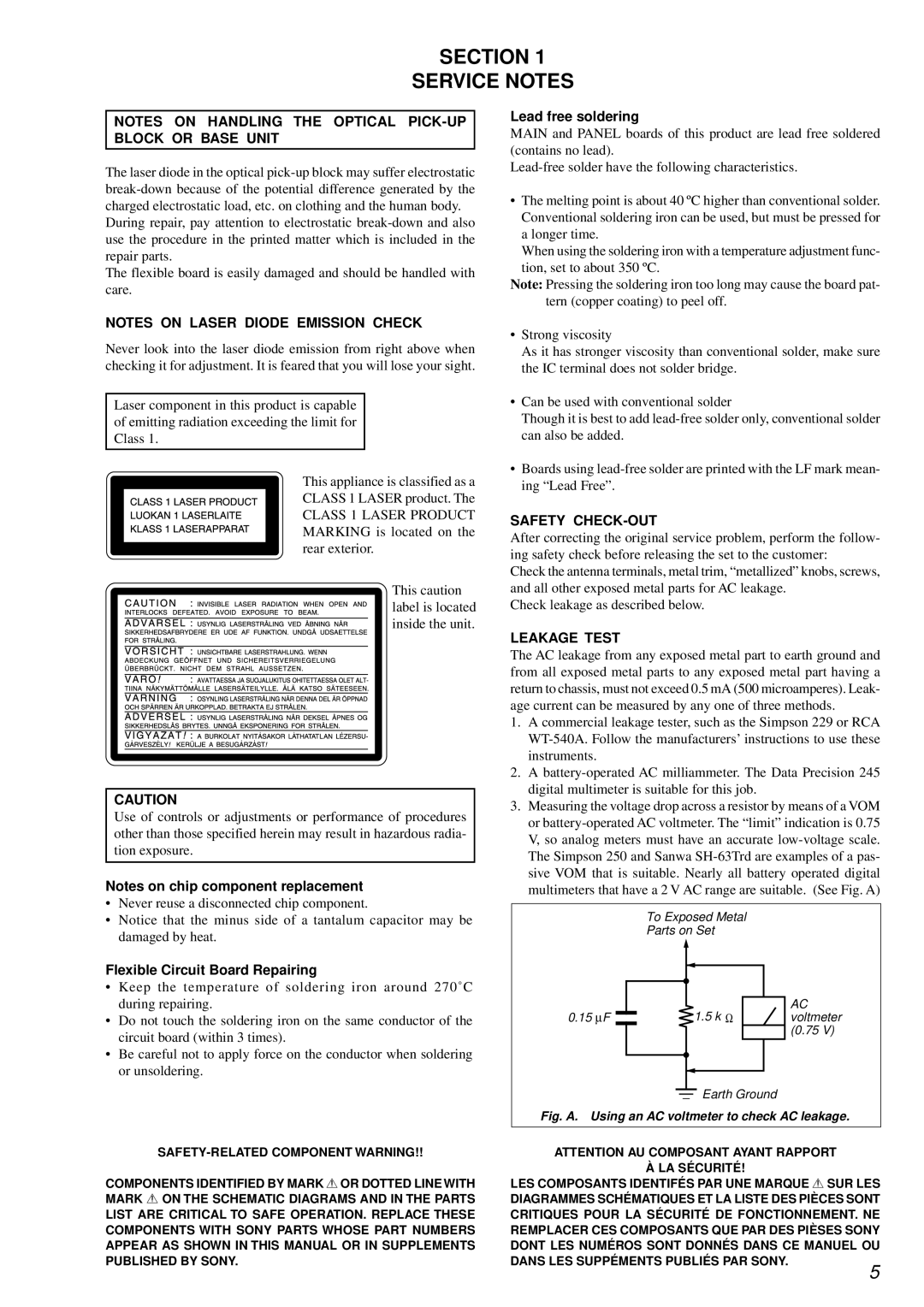
The AC leakage from any exposed metal part to earth ground and from all exposed metal parts to any exposed metal part having a return to chassis, must not exceed 0.5 mA (500 microamperes). Leak- age current can be measured by any one of three methods.
1.A commercial leakage tester, such as the Simpson 229 or RCA
2.A
3.Measuring the voltage drop across a resistor by means of a VOM or
To Exposed Metal
Parts on Set
0.15 ∝F |
|
|
| 1.5 k Ω | AC |
|
|
| voltmeter | ||
|
|
|
|
| (0.75 V) |
|
|
|
|
|
|
Earth Ground
Fig. A. Using an AC voltmeter to check AC leakage.
ATTENTION AU COMPOSANT AYANT RAPPORT
À LA SÉCURITÉ!
LES COMPOSANTS IDENTIFÉS PAR UNE MARQUE 0 SUR LES
DIAGRAMMES SCHÉMATIQUES ET LA LISTE DES PIÈCES SONT CRITIQUES POUR LA SÉCURITÉ DE FONCTIONNEMENT. NE REMPLACER CES COMPOSANTS QUE PAR DES PIÈSES SONY DONT LES NUMÉROS SONT DONNÉS DANS CE MANUEL OU
DANS LES SUPPÉMENTS PUBLIÉS PAR SONY.
5