4-6. FUNCTIONS OF OTHER BUTTONS
Function | Contents | |
|
| |
PLAY | Sets continuous playback when pressed in the STOP state. When pressed during continuous | |
playback, the tracking servo turns ON/OFF. | ||
| ||
|
| |
STOP | Stops continuous playback and continuous recording. | |
|
| |
FF | The sled moves to the outer circumference only when this is pressed. | |
|
| |
FR | The sled moves to the inner circumference only when this is pressed. | |
|
| |
SCROLL | Switches between the pit and groove modes when pressed. | |
|
| |
PLAYMODE | Switches the spindle servo mode (CLV S y CLV A). | |
|
| |
DISPLAY | Switches the displayed contents each time the button is pressed. | |
|
| |
x/Z “PGM” | Ejects the disc. | |
|
| |
x/Z | Exits the test mode. | |
|
| |
REPEAT | Resets the software. | |
|
| |
REC | Switches between recording start and stop if all servos are ON | |
|
| |
CLEAR | Differentiates the disc type (High reflective aluminum: CD/low reflection: MD) | |
|
| |
TIME | Switches between the error rate and motor modes | |
|
|
4-7. TEST MODE DISPLAYS
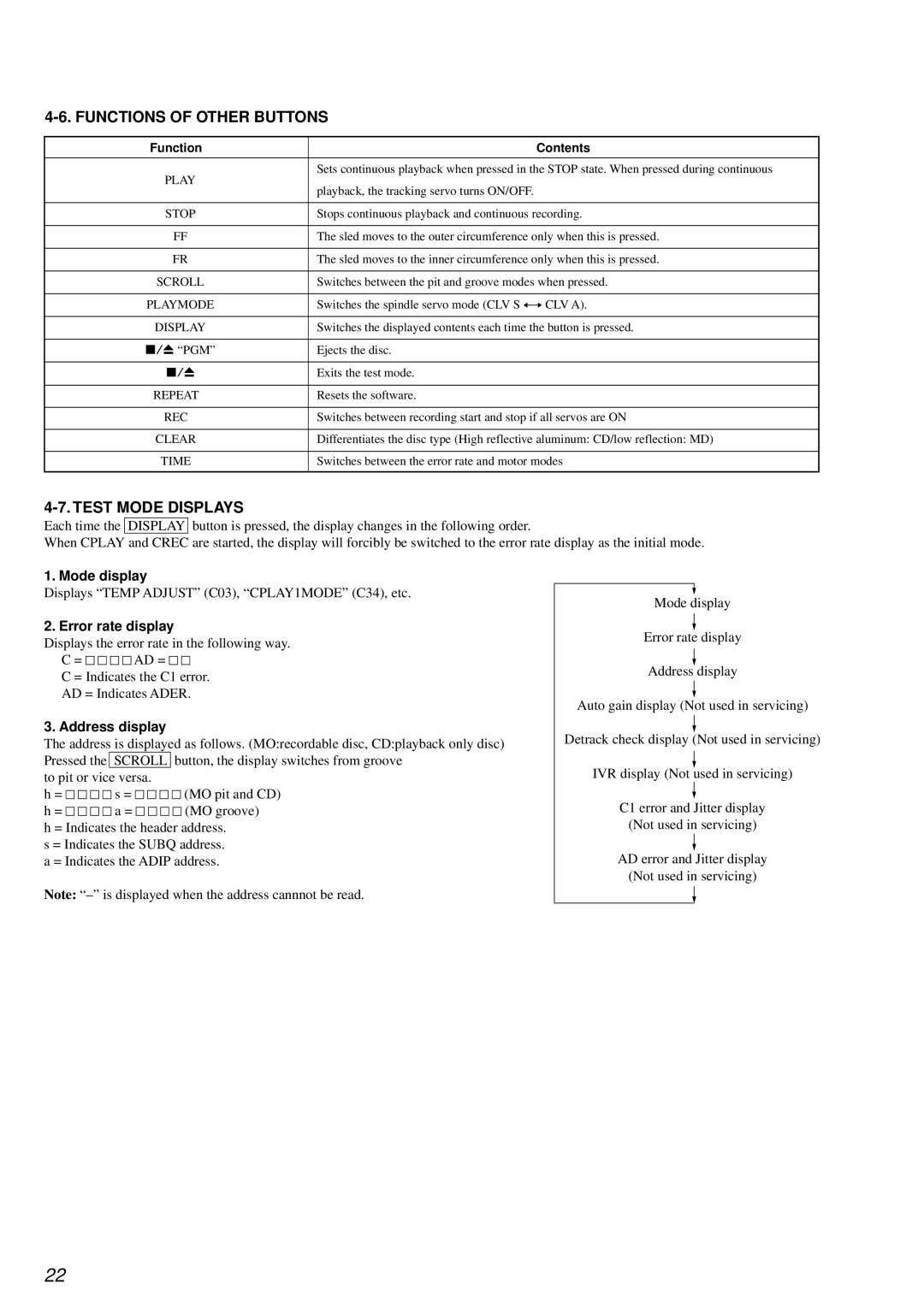
Each time the DISPLAY button is pressed, the display changes in the following order.
When CPLAY and CREC are started, the display will forcibly be switched to the error rate display as the initial mode.
1. Mode display
Displays “TEMP ADJUST” (C03), “CPLAY1MODE” (C34), etc.
2. Error rate display
Displays the error rate in the following way.
C = ![]()
![]()
![]()
![]()
![]()
![]()
![]()
![]() AD =
AD = ![]()
![]()
![]()
![]()
C = Indicates the C1 error.
AD = Indicates ADER.
3. Address display
The address is displayed as follows. (MO:recordable disc, CD:playback only disc) Pressed the SCROLL button, the display switches from groove
to pit or vice versa.
h = ![]()
![]()
![]()
![]() s =
s = ![]()
![]()
![]()
![]() (MO pit and CD)
(MO pit and CD)
h = ![]()
![]()
![]()
![]()
![]()
![]()
![]()
![]() a =
a = ![]()
![]()
![]()
![]()
![]()
![]()
![]()
![]() (MO groove) h = Indicates the header address.
(MO groove) h = Indicates the header address.
s = Indicates the SUBQ address. a = Indicates the ADIP address.
Note:
Mode display
Error rate display
Address display
Auto gain display (Not used in servicing)
Detrack check display (Not used in servicing)
IVR display (Not used in servicing)
C1 error and Jitter display
(Not used in servicing)
AD error and Jitter display
(Not used in servicing)
22