5-7. INITIAL SETTING OF ADJUSTMENT VALUE
Note:
Mode which sets the adjustment results recorded in the
If initial setting is performed, perform all adjustments again ex- cluding the temperature compensation offset adjustment.
For details of the initial setting, refer to
Setting Procedure :
1.Rotate the AMS knob to display “ADJ CLEAR” (C28).
2.Press the @/1 button. “Complete!” will be displayed momen- tarily and initial setting will be executed, after which “ADJ CLEAR” (C28) will be displayed.
INFORMATION
The Iop (C28) data can be recorded in the
Recording Procedure :
1.While pressing the AMS knob and x/Z button, connect the power plug to the outlet, and release the AMS knob and x/Z button.
2.Rotate the AMS knob to display “[Service]”, and press the @/1 button.
3.Rotate the AMS knob to display “Iop Write” (C05), and press the @/1 button.
4.The display becomes Ref=@@@.@ (@ is an arbitrary number) and the numbers which can be changed will blink.
5.Input Iop value written on the optical
6.When the @/1 button is pressed, the display becomes “Measu=@@@.@” (@ is an arbitrary number).
7.As the adjustment results are recorded for the 6 value. Leave it as it is and press the @/1 button.
8.“Complete! !” will be displayed momentarily. The value will be recorded in the
Display Procedure :
1.Rotate the AMS knob to display “Iop Read” (C26).
2.“@@.@/##.#” is displayed and the recorded contents are dis- played.
@@.@ indicates Iop value labeled on the
##.# indicates Iop value after adjustment
3. To end, press the x/Z button to display “Iop Read” (C26).
5-9. TEMPERATURE COMPENSATION OFFSET ADJUTMENT
Save the temperature data at that time in the
Note :
1.Usually, do not perform this adjustment.
2.Perform this adjustment in an ambient temperature of 22 ˚C to 28 ˚C. Perform it immediately after the power is turned on when the internal temperature of the unit is the same as the ambient temperature of 22 ˚C to 28 ˚C.
3.When D101 has been replaced, perform this adjustment after the temperature of this part has become the ambient tempera- ture.
Adjusting Procedure :
1.Rotate the AMS knob and display “TEMP ADJUST” (C03).
2.Press the @/1 button and select the “TEMP ADJUST” (C03) mode.
3.“TEMP = ![]()
![]()
![]()
![]() [OK]” and the current temperature data will be displayed.
[OK]” and the current temperature data will be displayed.
4.To save the data, press the @/1 button.
When not saving the data, press the x/Z button.
5.When the @/1 button is pressed, “TEMP = ![]()
![]() SAVE” will be displayed and turned back to “TEMP ADJUST” (C03) display then. When the x/Z button is pressed, “TEMP ADJUST” (C03) will be displayed immediatelly.
SAVE” will be displayed and turned back to “TEMP ADJUST” (C03) display then. When the x/Z button is pressed, “TEMP ADJUST” (C03) will be displayed immediatelly.
Specified Value :
The “TEMP = ![]()
![]() ” should be within “E0 - EF”, “F0 - FF”, “00 - 0F”, “10 - 1F” and “20 - 2F”.
” should be within “E0 - EF”, “F0 - FF”, “00 - 0F”, “10 - 1F” and “20 - 2F”.
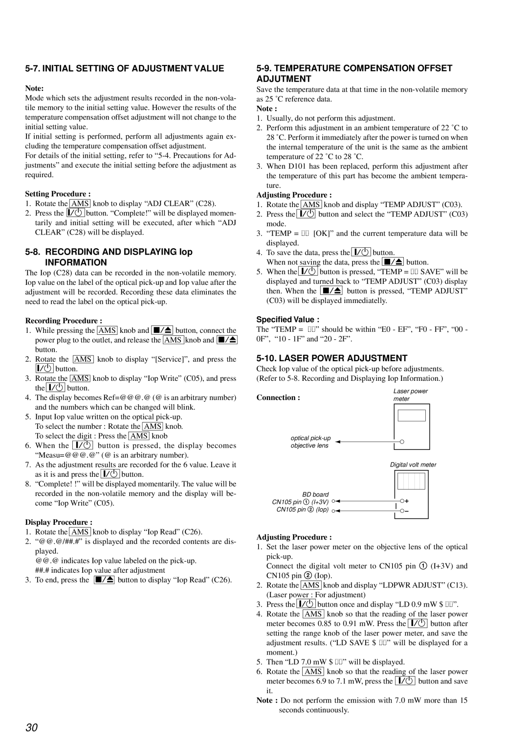
5-10. LASER POWER ADJUSTMENT
Check Iop value of the optical
Laser power
Connection :meter
optical
Digital volt meter
BD board
CN105 pin 1 (I+3V)
CN105 pin 2 (Iop)
Adjusting Procedure :
1.Set the laser power meter on the objective lens of the optical
Connect the digital volt meter to CN105 pin 1 (I+3V) and CN105 pin 2 (Iop).
2.Rotate the AMS knob and display “LDPWR ADJUST” (C13). (Laser power : For adjustment)
3.Press the @/1 button once and display “LD 0.9 mW $ ![]()
![]() ”.
”.
4.Rotate the AMS knob so that the reading of the laser power meter becomes 0.85 to 0.91 mW. Press the @/1 button after setting the range knob of the laser power meter, and save the adjustment results. (“LD SAVE $ ![]()
![]() ” will be displayed for a moment.)
” will be displayed for a moment.)
5.Then “LD 7.0 mW $ ![]()
![]() ” will be displayed.
” will be displayed.
6.Rotate the AMS knob so that the reading of the laser power meter becomes 6.9 to 7.1 mW, press the @/1 button and save
it.
Note : Do not perform the emission with 7.0 mW more than 15 seconds continuously.
30