4-5. SELECTING THE TEST MODE
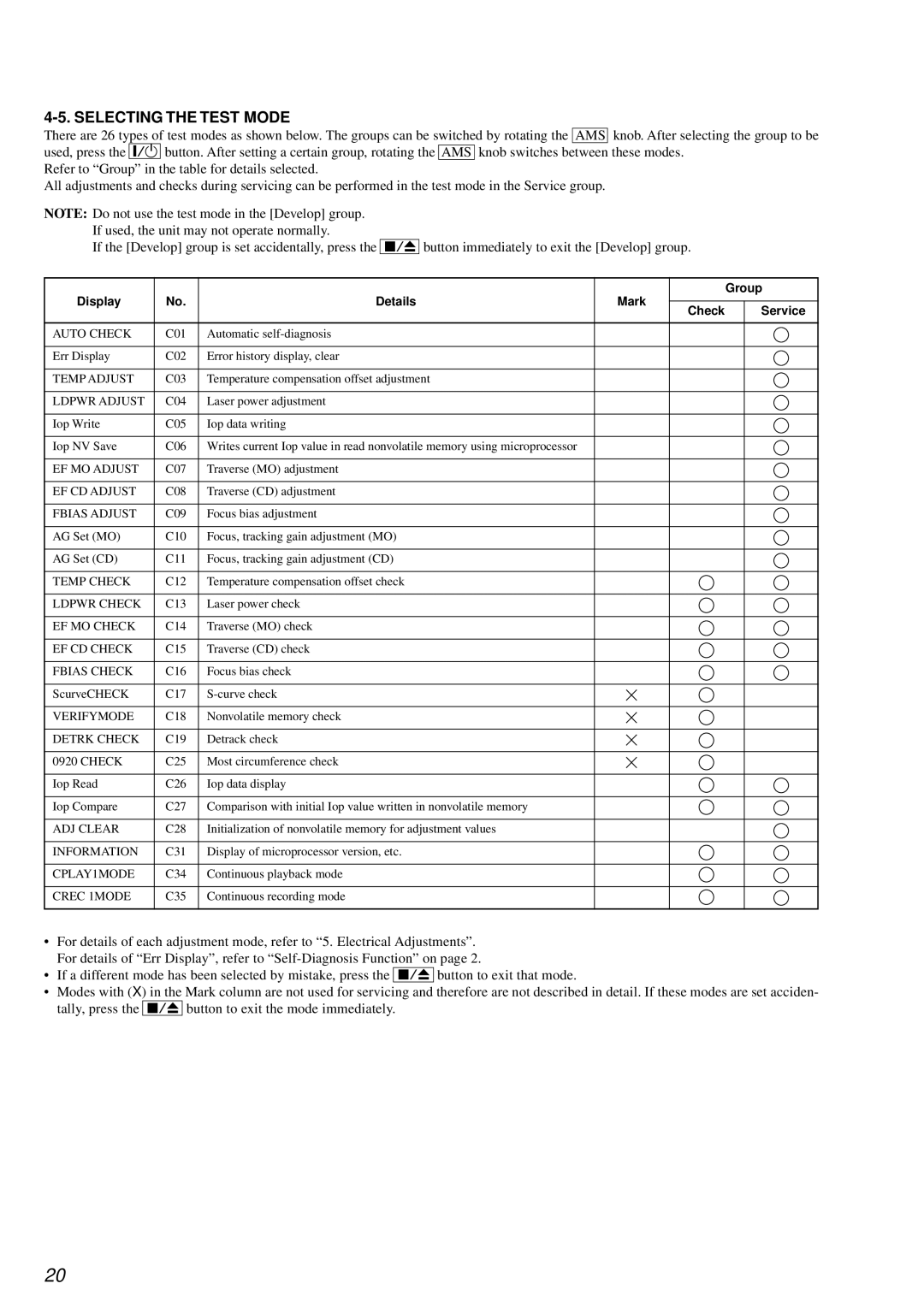
There are 26 types of test modes as shown below. The groups can be switched by rotating the AMS knob. After selecting the group to be used, press the @/1 button. After setting a certain group, rotating the AMS knob switches between these modes.
Refer to “Group” in the table for details selected.
All adjustments and checks during servicing can be performed in the test mode in the Service group.
NOTE: Do not use the test mode in the [Develop] group. If used, the unit may not operate normally.
If the [Develop] group is set accidentally, press the
x/Z
button immediately to exit the [Develop] group.
Display | No. | Details | Mark | Group | |
Service | |||||
|
|
| Check | ||
AUTO CHECK | C01 | Automatic |
|
| |
Err Display | C02 | Error history display, clear |
|
| |
TEMP ADJUST | C03 | Temperature compensation offset adjustment |
|
| |
LDPWR ADJUST | C04 | Laser power adjustment |
|
| |
Iop Write | C05 | Iop data writing |
|
| |
Iop NV Save | C06 | Writes current Iop value in read nonvolatile memory using microprocessor |
|
| |
EF MO ADJUST | C07 | Traverse (MO) adjustment |
|
| |
EF CD ADJUST | C08 | Traverse (CD) adjustment |
|
| |
FBIAS ADJUST | C09 | Focus bias adjustment |
|
| |
AG Set (MO) | C10 | Focus, tracking gain adjustment (MO) |
|
| |
AG Set (CD) | C11 | Focus, tracking gain adjustment (CD) |
|
| |
TEMP CHECK | C12 | Temperature compensation offset check |
|
| |
LDPWR CHECK | C13 | Laser power check |
|
| |
EF MO CHECK | C14 | Traverse (MO) check |
|
| |
EF CD CHECK | C15 | Traverse (CD) check |
|
| |
FBIAS CHECK | C16 | Focus bias check |
|
| |
ScurveCHECK | C17 |
|
| ||
VERIFYMODE | C18 | Nonvolatile memory check |
|
| |
DETRK CHECK | C19 | Detrack check |
|
| |
0920 CHECK | C25 | Most circumference check |
|
| |
Iop Read | C26 | Iop data display |
|
| |
Iop Compare | C27 | Comparison with initial Iop value written in nonvolatile memory |
|
| |
ADJ CLEAR | C28 | Initialization of nonvolatile memory for adjustment values |
|
| |
INFORMATION | C31 | Display of microprocessor version, etc. |
|
| |
CPLAY1MODE | C34 | Continuous playback mode |
|
| |
CREC 1MODE | C35 | Continuous recording mode |
|
|
•For details of each adjustment mode, refer to “5. Electrical Adjustments”. For details of “Err Display”, refer to
•If a different mode has been selected by mistake, press the x/Z button to exit that mode.
•Modes with (X) in the Mark column are not used for servicing and therefore are not described in detail. If these modes are set acciden- tally, press the x/Z button to exit the mode immediately.
20
