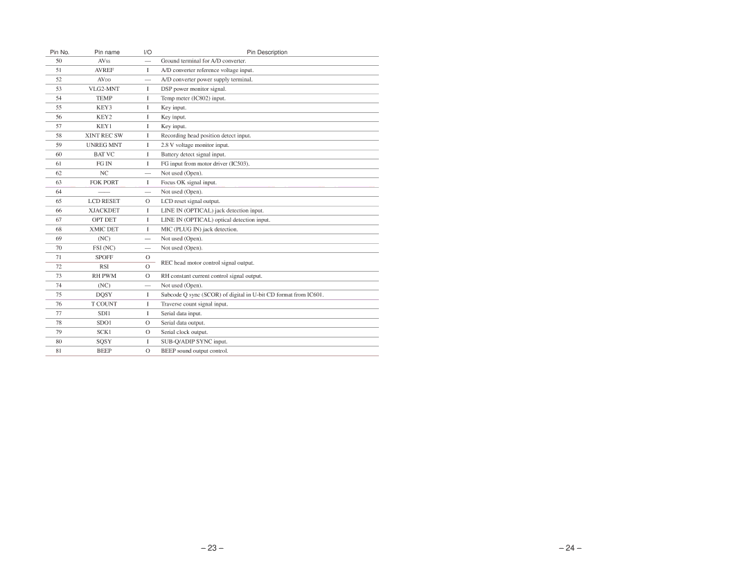
Pin No. | Pin name | I/O |
| Pin Description | |
50 | AVSS | — | Ground terminal for A/D converter. | ||
|
|
|
|
| |
51 | AVREF | I |
| A/D converter reference voltage input. | |
|
|
|
| ||
52 | AVDD | — | A/D converter power supply terminal. | ||
|
|
|
|
| |
53 | I |
| DSP power monitor signal. | ||
|
|
|
|
| |
54 | TEMP | I |
| Temp meter (IC802) input. | |
|
|
|
|
| |
55 | KEY3 | I |
| Key input. | |
|
|
|
|
| |
56 | KEY2 | I |
| Key input. | |
|
|
|
|
| |
57 | KEY1 | I |
| Key input. | |
|
|
|
|
| |
58 | XINT REC SW | I |
| Recording head position detect input. | |
|
|
|
|
| |
59 | UNREG MNT | I |
| 2.8 V voltage monitor input. | |
|
|
|
|
| |
60 | BAT VC | I |
| Battery detect signal input. | |
|
|
|
|
| |
61 | FG IN | I |
| FG input from motor driver (IC503). | |
|
|
|
|
| |
62 | NC | — |
| Not used (Open). | |
|
|
|
|
| |
63 | FOK PORT | I |
| Focus OK signal input. | |
|
|
|
|
| |
64 |
|
| — Not used (Open). | ||
|
|
|
|
| |
65 | LCD RESET | O |
| LCD reset signal output. | |
|
|
|
|
| |
66 | XJACKDET | I |
| LINE IN (OPTICAL) jack detection input. | |
|
|
|
|
| |
67 | OPT DET | I |
| LINE IN (OPTICAL) optical detection input. | |
|
|
|
|
| |
68 | XMIC DET | I |
| MIC (PLUG IN) jack detection. | |
|
|
|
|
| |
69 | (NC) | — |
| Not used (Open). | |
|
|
|
|
| |
70 | FSI (NC) | — |
| Not used (Open). | |
|
|
|
|
| |
71 | SPOFF | O |
| REC head motor control signal output. | |
|
|
|
| ||
72 | RSI | O | |||
|
| ||||
|
|
|
|
| |
73 | RH PWM | O |
| RH constant current control signal output. | |
|
|
|
|
| |
74 | (NC) | — |
| Not used (Open). | |
|
|
|
|
| |
75 | DQSY | I |
| Subcode Q sync (SCOR) of digital in | |
|
|
|
|
| |
76 | T COUNT | I |
| Traverse count signal input. | |
|
|
|
|
| |
77 | SDI1 | I |
| Serial data input. | |
|
|
|
|
| |
78 | SDO1 | O |
| Serial data output. | |
|
|
|
|
| |
79 | SCK1 | O |
| Serial clock output. | |
|
|
|
|
| |
80 | SQSY | I |
| ||
|
|
|
|
| |
81 | BEEP | O |
| BEEP sound output control. | |
|
|
|
|
| |
82 | XLAT | O |
| Latch output. | |
|
|
|
|
| |
83 | NC | — |
| Not used (Open). | |
|
|
|
| ||
84 | TEX | — | Not used (Fixed at “L”). | ||
|
|
|
| ||
85 | TX | — | Not used (Fixed at “L”). | ||
|
|
|
|
| |
86 | VSS | — |
| Ground. | |
|
|
|
| ||
87 | VDD | — | Power supply pin (+2.8V). | ||
|
|
|
| ||
88 | NC | — | Not used (Fixed at “H”). | ||
|
|
|
|
| |
89 | XCS ADA | O |
| A/D, D/A converter chip select output. | |
|
|
|
| ||
90 | XPD ADA | O | A/D, D/A converter power down signal output. H : Power down | ||
|
|
|
|
| |
91 | KEY ON | O |
| SLEEP : L, action : H. | |
|
|
|
| ||
92 | XNIMH DET (NC) | — | Not used (Open). (Battery detect switch input.) | ||
|
|
|
|
| |
93 | A MUTE | O |
| Analog mute control. H : Mute | |
|
|
|
|
| |
94 | XOPT CTL | O |
| Power supply control output for an optical input. | |
|
|
|
|
| |
95 | FFCLR | O |
| Flip flop clear signal output. | |
|
|
|
|
| |
96 | XCE NV | O |
| EEPROM chip select output. | |
|
|
|
|
| |
97 | SENS | I |
| SENS input. | |
|
|
|
|
| |
98 | LDON | O |
| “H” : APC circuit ON, “L” : APC circuit OFF | |
|
|
|
|
| |
99 | XSHOCK | I |
| Track jump detection input from IC601. | |
|
|
|
|
| |
100 | CLV STB | O |
| CLV drive control signal output. | |
|
|
|
|
| |
– 23 – | – 24 – |