MZ-R37
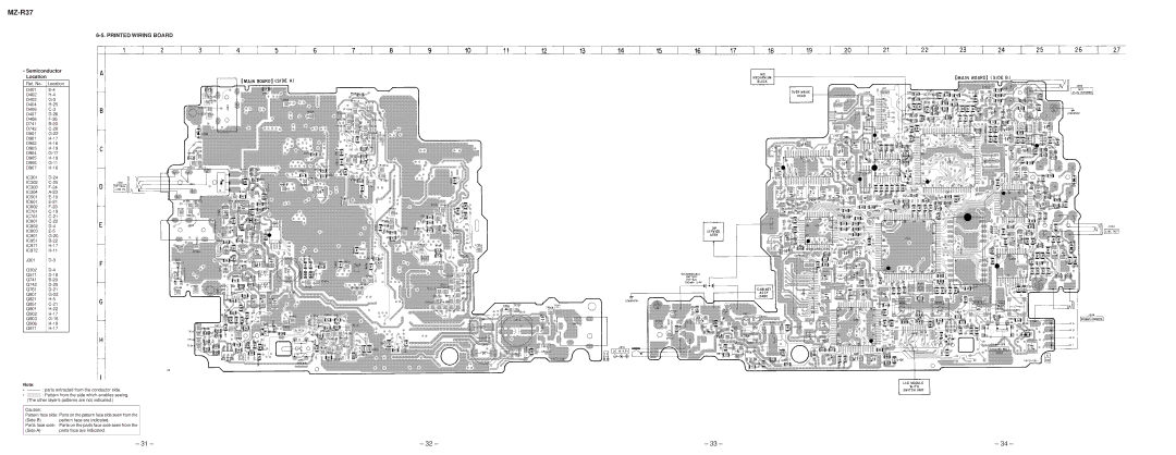
6-5. PRINTED WIRING BOARD
•Semiconductor Location
Ref. No. | Location |
D401 | |
D402 | |
D403 | |
D404 | |
D406 | |
D407 | |
D408 | |
D741 | |
D742 | |
D801 | |
D901 | |
D902 | |
D903 | |
D904 | |
D905 | |
D906 | |
D907 | |
IC301 | |
IC302 | |
IC303 | |
IC304 | |
IC501 | |
IC601 | |
IC602 | |
IC701 | |
IC761 | |
IC801 | |
IC802 | |
IC803 | |
IC901 | |
IC951 | |
IC971 | |
IC972 | |
J301 | |
Q302 | |
Q571 | |
Q741 | |
Q742 | |
Q761 | |
Q801 | |
Q821 | |
Q851 | |
Q901 | |
Q902 | |
Q903 | |
Q906 | |
Q971 | |
|
|
Note:
•Y : parts extracted from the conductor side.
•b : Pattern from the side which enables seeing. (The other layer’s patterns are not indicated.)
Caution:
Pattern face side: Parts on the pattern face side seen from the
(Side B) pattern face are indicated.
Parts face side: Parts on the parts face side seen from the
(Side A) | parts face are indicated. |
– 31 – | – 32 – | – 33 – | – 34 – |
