VPL-HS1 World VPL-HS1FP World
Warnung
Gooi de batterij niet weg, maar lever hem in als KCA
Page
Table of Contents
Block Diagrams
Semiconductors
Spare Parts
Diagrams
Page
LCD Video Projector
Table of Contents
Installing
Precautions
Unpacking
Projector
Installing the Projector and a
Before Setting Up Projector
Screen
Connecting with video equipment
Adjusting Picture Size Position
Connecting Using the Optional
Connecting Using the Optional Signal Interface Cables
Using the zoom lever
Plug the AC power cord into a
Adjuster
Adjust to correct the trapezoidal distortion
Step
Selecting
Menu Language
Projecting
Picture on
Screen
Picture Viewing
Mode
Operation through the Menus
Menu Configurations
Menu Items
On an item
Adjusting Picture Quality of a Signal from the Computer
About the Preset Memory No
Inserting a Memory Stick
About a Memory Stick
Using the MS Memory Stick Home
Displaying Index Pictures on the Full Screen
Displaying a Full- Screen Picture
Displaying the Index Menu
Protecting an Important Still Picture
Rotating a Still Picture
Setting the Startup Picture
Registering a Still Picture as
Startup Picture
Initializing a
Memory Stick
Deleting a Still Picture
Others
Troubleshooting
Indicators
Replacing the Air Filter
Replacing Lamp
System
Specifications
Preset Signals
Location Controls
Front
Rear
Index
Remote control
Projector Stand
Specifications
IFU-HS1
Signal Interface Unit
How to Use
Specifications
Supplied Accessory
Board Layout
Section Service Informations
Disassembly and Extension Boards
Hood Block Assy Removal
Board Removal
MS Board Removal
BC Board Removal
BB and NF Boards Removal
Remove the Optics block assy. Refer to Sec.2-2-7
Optics block assy Removal
NR Board Removal
BA Board Removal
Hi-voltage block and G Board Removal
Prism Block Assy and In-polarizer Removal
Projection Lens Removal
Extension Boards and Extension Cables
KIT ASSYA-1502-036-A
Extension Boards and Extension Cables Connecti
BC Board
BB and MS Boards
BA Board
Board
Use a proper power cord for your local power supply
Power Cord
Optical Unit Adjustment
COM Adjustment
Factory Mode Setting
Preparations
Status Memory
Adjustment Item Initialize Data
Memory Video Memory
Depends on the color system and the input terminal
Top/bottom
Service Knowhow
After Replacing the Prism Block
After Replacing the Board
Signal Level Adjustment White Balance Adjustment
White Balance Adjustment on Servicing
MID Mode of INPUT-A
High Mode of INPUT-A
MID/HIGH/LOW Mode of Video
LOW Mode of INPUT-A
Memory
Memory
Page
Section Semiconductors
TOP View
HN1C01FU-TE85R
Transistor
Diode
Standardization of Parts
Safety Related Components Warning w
Stock of Parts
Units for Capacitors, Inductors and Resistors
Cover
Cover Exploded Views
Chassis
Chassis
Cover ASSY, Lamp
HOLDER,WIRE
SCREW, M3
Washer M3 PLA
Stand
Stand
Optics
Optics
LENS, MAIN-2
BASE, Unit
Fastener OPT, Mirror
MIRROR, B-CHANNEL
Stand SU-HS1
Stand
Mountec C.BOARD,BA Compl
Electrical Parts List
CAPACITOR, Elect 100MF/16V
CAPACITOR,ELECT 2.2MF/50V
Transistor 2SA1162-G
CAPACITOR,ELECT 47M/6.3
INDUCTOR,FERRITE Bead
Inductor 4.7UH
R141
BB Board
Ceramic 0.1MF
CONNECTOR, Board to Board
IC 74VHC14MTCX
IC PQ2TZ15U
Description R414
CAPACITOR,ELECT 10MF/16V
Mounted Circuit BOARD, BC
CAPACITOR, C.CERAMIC 2.2MF
CAPACITOR,ELECT 10MF/35V
C316
PIN, Connector 7P
PIN,CONNECTOR SMD 10P
PIN,CONNECTOR 3P
PIN, Connector 5P
Transistor 2SC3326N-A
IC S-80828ANNP-EDR-T2
CONDUCTOR, Chip
R609
PLUG,CONNECTOR 7P
PLUG,CONNECTOR 12P
Board
Diode RM11C
Diode D2FS4-TA
Diode RD33M-B
Diode D10SC6M Recti
Diode D10SC4M
MS Board
SWITCH, Tactile
Dual
PC Board
Diode UMZ6.8N-T106
Diode CL-190B1-X-T
Diode UDZSTE-173.9B
IC HM62V16256CLTT-5SLZ
OSCILLATOR, Crystal
NF Board
C901
Diode 1SS226
Diode RD9.1SB
FERRITE, EMI SMD
Diode RD9.1SB2
IC LT1399CGNTR
IC 74VHC240MTCX
R443
R630
SU-HS1
Paking Materials
Page
B0ARD
Color Decorder
Reset
Yout Buffer CVBS/Y2
Cbout Buffer CVBS/Y1
BB Block
KEY0 Power LED SUB5V Temp LED Lamp LED
Volume Control
Speaker
SP-R SR-L
Block
MS Block
3D GAMMA&TG,LCD Driver
VPL-HS1
Diagrams
Frame Schematic Diagram
Frame2/2 Frame2/2
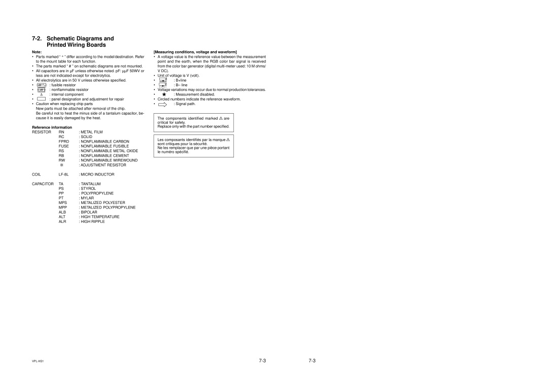
Reference information
Schematic Diagrams and Printed Wiring Boards
NJM2533M IC103,IC105
MC141627FT IC202
BA033F-E2 IC301
CXA1875AM IC201
BA 1/3
VEH1 VEH2 VEH3
BA 2/3
Cont
VEH1
BA 3/3
MK1714-01IC403
AD9884AKS-100 IC203 74VHC125MTCX IC204
LP29851M5X-3.3 IC202
80828ANNP IC401
BB 1/4
BB 2/4
BB 3/4
BB 4/4
CXA1846BN/T4 IC801
BC -B Side
Svrr
INVIN1
INVIN2
AUL A1 INP1 INN1
Side
80828ANNP IC303 LP2985IM5X-3.3 IC204 BA05FP-E2 IC103,104
M52749FP IC403
CXA3512R-T6 IC501,601,701
ADV7123KST140 IC404 TC7WH74FUTE12R IC108
Powerled
RES Powercont GND FWR
Pwreset B1 Txdpw GND I2C Interlace Picmute Pwosden
B10SUB+5V Romreset
Lampprot Psaveled Lampled Templed
Resetms Sircs
MD2 MD1
TXD RXD
Osden GE7
DA DAT to 4/7
Lcdhst
LCDHCK1
Video RR
DAC I2C
Video RG
Video RB
VSIG1
Vssgr
VSIG2
VSIG3
SIG4
SID FRP
SIG5
SIG6
Vcomout SHOUT1
Scen Vcom B
POSCTR1 POSCTR2
Status Dirctr
Bchip
R3152
MZ1540 IC2101
Power on
G1/2 G1/2
DC+
SUB +5V
G2/2 G2/2
Left
POWER-LED
Lamp Temp Psave
Right Down Enter Menu Input
297-29
74VHC240MTCX IC407
M52347FP IC405 CXA1875AX IC406
IN2B VCC
IN1A
IN2A
IN3B
A5V GND
AUDIO+B
Audio +B to 4/4
TP510CLP
2R-Y5 2B-Y5 +9V
VCC MAT GND MAT
2HS5 2VS5
HS2 VS2 HS3 VS3 PR3 PB3 HS4 VS4
B1 AUL
A1 AUL
A3 AUR
B3 AUR
GND1 VCC
Chip
WHT GND2 OUT
Fchip
TC7WH74FK IC815
MS -A Side
MS 1/3
101
MS 2/3
MS 3/3
Page
Safety CHECK-OUT
Sony Corporation