STANDING PILOT OPERATING INSTRUCTIONS (continued)
Manual Operation
1.Turn ON/OFF/REMOTE switch to REMOTE position.
2.Turn wall thermostat OFF.
3.Turn accessory,
Wall Thermostat Operation
1.Turn the ON/OFF/REMOTE switch to REMOTE position.
2.Turn accessory,
3.Turn wall thermostat ON and set appropriate temperature. Wall thermostat will cycle the appliance ON and OFF.
Installation of Remote Receiver
Place remote receiver on the floor of fireplace behind the louver as far forward as possible.
Attention: The velcro loop and hook are not necessary in this installation but can be used to secure remote receiver.
Refer to remote control installation and operating instructions for more details on remote control.
Millivolt Control
The valve regulator controls the burner pressure which should be checked at the pressure test point. Turn captured screw counter clockwise 2 or 3 turns and then place tubing to pressure gauge over test point (Use test point “A” closest to control knob). After taking pressure reading, be sure and turn captured screw clock- wise firmly to
Millivolt thermopile is self powered gas valve and does not re- quire 110 volts.
Check System Operation
Millivolt system and all individual components may be checked with a millivolt meter
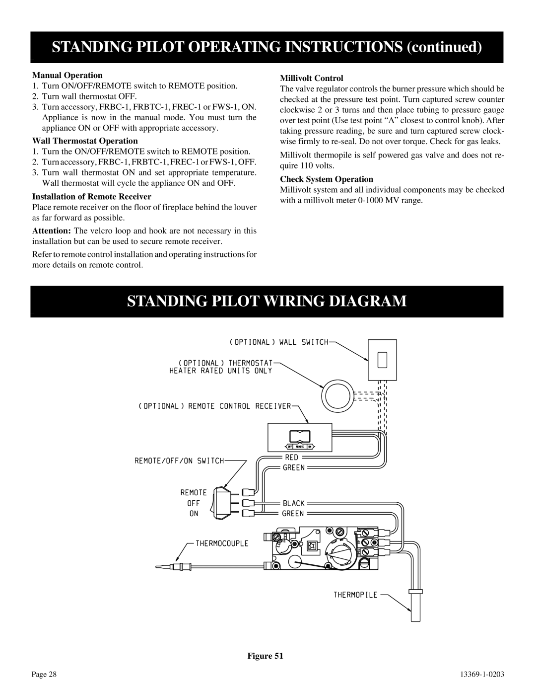
STANDING PILOT WIRING DIAGRAM
Figure 51
Page 28 |