ACCESSORY PARTS
The following accessory parts can be obtained from your Empire Comfort Systems, dealer. Should you need additional information beyond what your dealer can furnish, contact Empire Comfort Systems, Inc., Nine Eighteen Freeburg Ave., Belleville, Illinois 62222-
0529. |
|
|
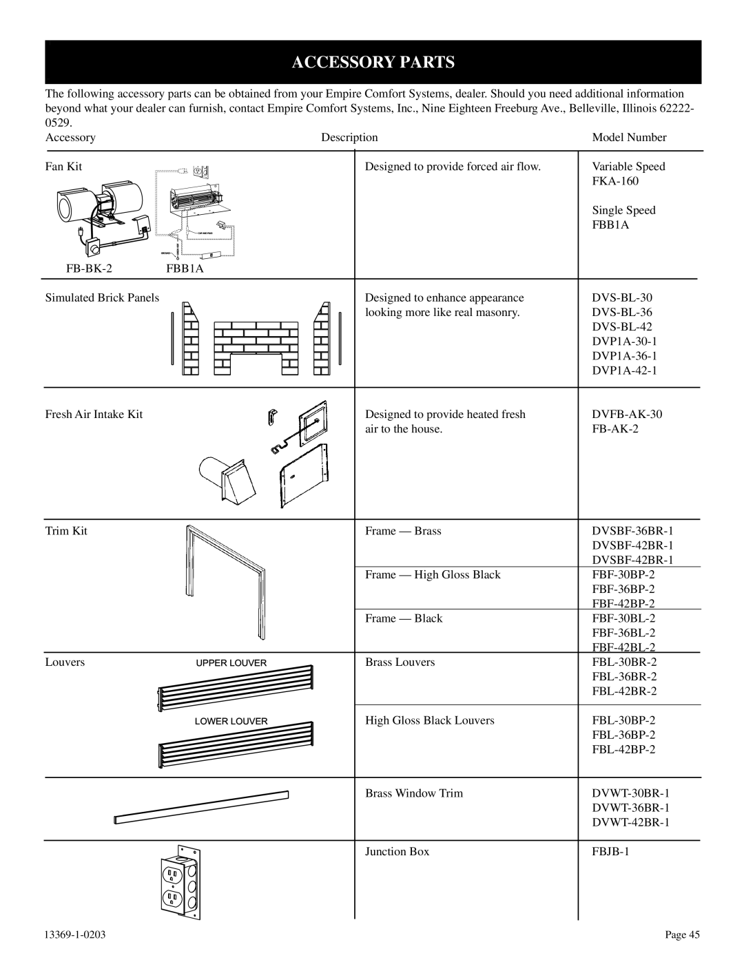
Accessory | Description | Model Number |
Fan Kit | Designed to provide forced air flow. | Variable Speed |
|
|
FBB1A |
| |
Simulated Brick Panels | Designed to enhance appearance | |
| looking more like real masonry. | |
|
|
|
|
| |
|
| |
|
|
Fresh Air Intake Kit
Designed to provide heated fresh air to the house.
Trim Kit
Frame — Brass
Frame — High Gloss Black
Frame — Black
Louvers | UPPER LOUVER |
Brass Louvers
LOWER LOUVER
High Gloss Black Louvers
Brass Window Trim
Junction Box
Page 45 |