VARIABLE SPEED BLOWER INSTALLATION INSTRUCTIONS
Optional
and
Factory Installed
1.If applicable, turn OFF electric supply to fireplace.
2.Lower bottom louver.
3.With a 5/16" socket, loosen but do not remove either left screw or right screw that attaches bottom louver to fireplace side.
4.When the screw is sufficiently loosened you will be able to pull and pivot the bottom louver out of fireplace.
5.Centered in the rear are two (2) weld studs which protrude upward into the bottom of fireplace for attachment of fan.
6.Insert fan into interior, bottom of fireplace. The clearance holes on fan mounting bracket must be facing toward the front of fireplace. Do not damage gas inlet supply line when fan is inserted into fireplace.
7.Align and place rear set of clearance holes on fan mounting bracket onto two (2) weld studs for direct vent 36/42 models or front set of clearance holes on fan mounting bracket onto two
(2) weld studs for other models.
8.Use two (2) wing nuts to attach blower to weld studs.
9.Depending on the appliance, you will remove the top louver(s) by one of the following methods.
First Method, Push up and outward to remove top louver. Second Method, Remove top louvers by grasping an individual
louver at each end and pivoting louver out of frame. Remove three (3) additional louvers in this same manner.
Attention: Steps 10 through 17 DO NOT apply to RF models.
10.Located in the right, front are two (2) weld studs which protrude upward into the bottom of fireplace for attachment of speed control.
11.Insert speed control into interior, bottom of fireplace. Align and place two (2) clearance holes on speed control onto two (2) weld studs.
12.Use two (2) wing nuts to attach speed control to weld studs.
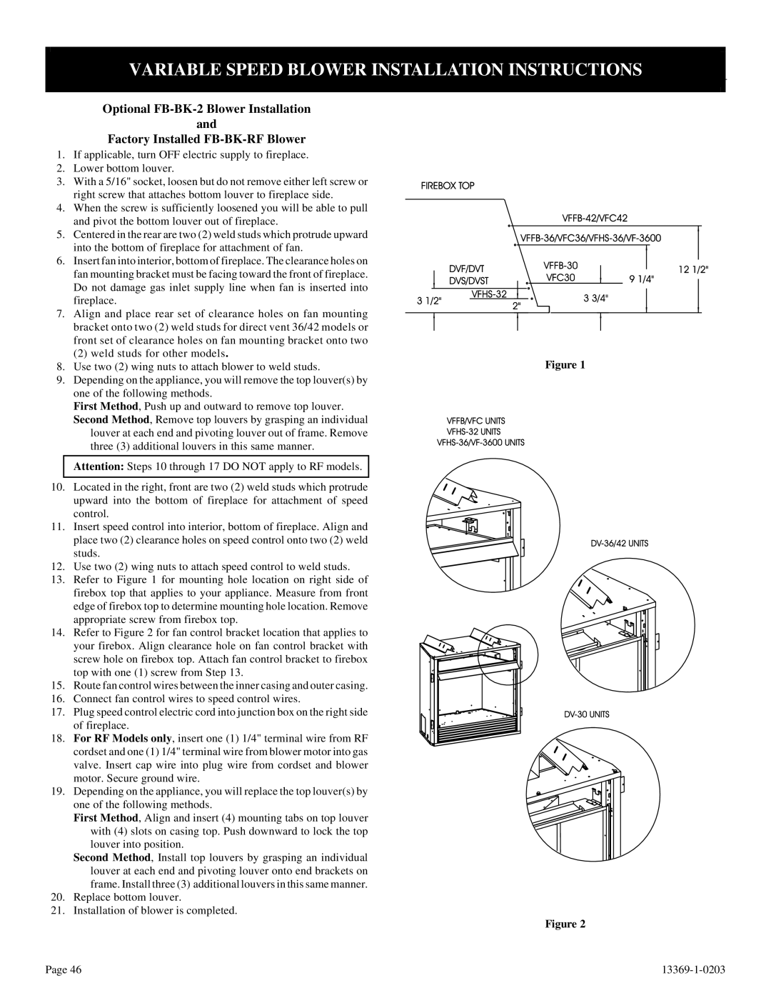
13.Refer to Figure 1 for mounting hole location on right side of firebox top that applies to your appliance. Measure from front edge of firebox top to determine mounting hole location. Remove appropriate screw from firebox top.
14.Refer to Figure 2 for fan control bracket location that applies to your firebox. Align clearance hole on fan control bracket with screw hole on firebox top. Attach fan control bracket to firebox top with one (1) screw from Step 13.
15.Route fan control wires between the inner casing and outer casing.
16.Connect fan control wires to speed control wires.
17.Plug speed control electric cord into junction box on the right side of fireplace.
18.For RF Models only, insert one (1) 1/4" terminal wire from RF cordset and one (1) 1/4" terminal wire from blower motor into gas valve. Insert cap wire into plug wire from cordset and blower motor. Secure ground wire.
19.Depending on the appliance, you will replace the top louver(s) by one of the following methods.
First Method, Align and insert (4) mounting tabs on top louver with (4) slots on casing top. Push downward to lock the top louver into position.
Second Method, Install top louvers by grasping an individual louver at each end and pivoting louver onto end brackets on frame. Install three (3) additional louvers in this same manner.
20.Replace bottom louver.
21.Installation of blower is completed.
Figure 1
Figure 2
Page 46 |