DIRECT VENT GAS FIREPLACE
The Tahoe Direct Vent Gas Fireplaces
TABLE OF CONTENTS
Section
Page
IMPORTANT SAFETY INFORMATION
LP-GASWARNING ODOR
SAFETY INFORMATION FOR USERS OF LP-GAS
Thats your signal to go into immediate action
NO ODOR DETECTED - ODOR FADE
Qualified Installing Agency
INTRODUCTION
Instructions to Installer
Installation in Residential Garages
SPECIFICATIONS
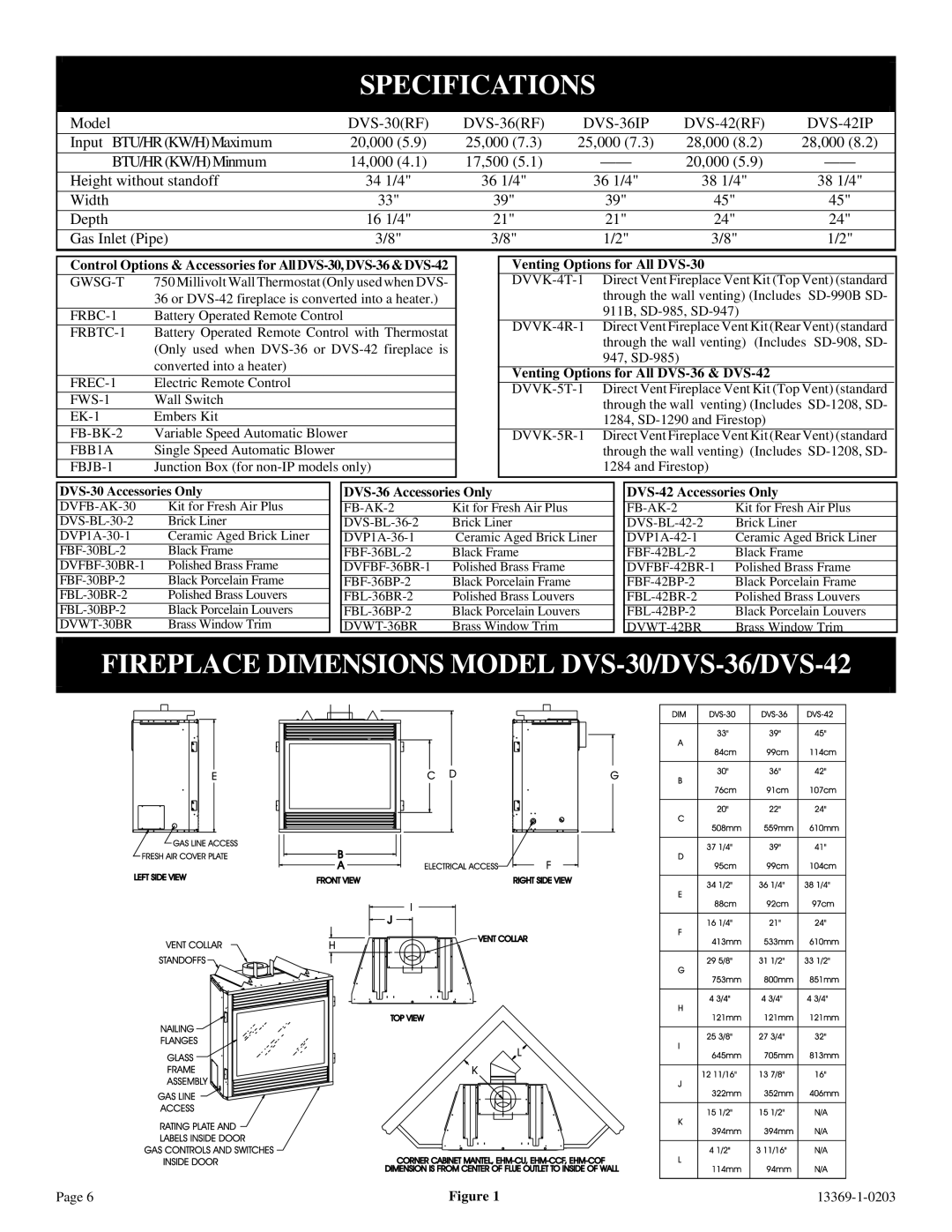
FIREPLACE DIMENSIONS MODEL DVS-30/DVS-36/DVS-42
Adapter Pipe Vertical Outlet
FIREPLACE COMPONENT INSTALLATION
HEATER BAFFLE IS USED ON DVS-36& DVS-42ONLY
Adapter Pipe Horizontal Outlet
Mantel Chart Figure
CLEARANCES
LOCATING FIREPLACE
Figure Clearances Figure
Recommended Gas Pipe Diameter
GAS SUPPLY
Installing a New Main Gas Cock
Pipe Length
Venting Graph Dimensions in Feet
INSTALLATION
VENTING FIREPLACE
To Use the Vent Graph Figure
Finishing Figure
Three 3 basic types of installations
Framing Figure
Vent Runs Figures 14, 15, 16, 17 and
VERTICAL, 90 ELBOW TO HORIZONTAL OUT THE
INSTALLATION continued
VERTICAL, 90 ELBOW WITH HORIZONTAL
TERMINATION
HORIZONTAL OUT THE WALL
CORNER INSTALLATION VERTICAL, 90 ELBOW TO
CORNER INSTALLATION HORIZONTAL, 45 ELBOW
TO HORIZONTAL OUT THE WALL
Venting with One 1 90 Elbow or Two 2 90 Elbows
INSTALLATION continued
CHART 1 Figures 20 and
Figure Figure Positioning the Fireplace
Cutting the Hole Figures 22 and
TERMINATION CLEARANCES
Figure Vertical Sidewall Installations
VENT CLEARANCES
13369-1-0203
Page
Venting Components
VENT SYSTEM IDENTIFICATION
Installing Vent Components Figure
The inner flue joints do not require any sealant
DVS-30FRAMING AND FINISHING
Installing Support Brackets Figure
Installing Firestops Figures 30, 31, 32 and
DVS-30FRAMING AND FINISHING continued
DVS-36& DVS-42FRAMING AND FINISHING
Installing Support Brackets Figure
Installing Firestops Figures 35, 36, 37 and
DVS-36& DVS-42FRAMING AND FINISHING continued
HORIZONTAL TERMINATION For All Models
Installing the Vent System in a Chase
VERTICAL TERMINATION For All Models
General Maintenance
Determining Minimum Vent Height Above the Roof
Reassembly and Resealing Vent Pipe System
LOG PLACEMENT
VERTICAL TERMINATION For All Models continued
Vertical Through the Roof Applications Figure
DVS-36and DVS-42Log Placement Figure
Glass Replacement
DVS-30Log Placement Figure
Placement of Glowing Embers Rock Wool Figure
STANDING PILOT OPERATING INSTRUCTIONS
FLAME APPEARANCE
750 Millivolt System Figures 48 and
Electric 120 volt Operated Remote Control, FREC-1
RECOMMENDED WIRE GAUGES
Wall Switch, FWS-1
Figure Initial Lighting
Installation of Remote Receiver
STANDING PILOT WIRING DIAGRAM
STANDING PILOT OPERATING INSTRUCTIONS continued
Manual Operation
LIGHTING INSTRUCTIONS
FOR YOUR SAFETY READ BEFORE LIGHTING
STANDING PILOT LIGHTING INSTRUCTIONS
TO TURN OFF GAS TO FIREPLACE
6.Glass soots
STANDING PILOT TROUBLESHOOTING
4.Frequent pilot outage problem
7.Flame burns blue and lifts off main burner
DVS-36& DVS-42INTERMITTENT PILOT WIRING DIAGRAM
Installation of Remote Receiver
ELECTRICAL CONNECTION Figure
TO TURN OFF GAS TO APPLIANCE
FOR YOUR SAFETY READ BEFORE LIGHTING
LIGHTING INSTRUCTIONS
OPERATION
DVS-36& DVS-42INTERMITTENT PILOT TROUBLESHOOTING
SPECIFICATIONS
TRIAL FOR IGNITION
S8600H NORMAL OPERATING SEQUENCE
DVS-36& DVS-42INTERMITTENT PILOT TROUBLESHOOTING
Safety Lockout
Main Burner Operation
Ignition System Checks
ARC LENGTH
ACTION
S8600H TROUBLESHOOTING GUIDE
Note If S8600H goes into lockout, reset system
Transmitter Signal
RF STANDING PILOT OPERATING INSTRUCTIONS
Features
LED Troubleshooting
RF WIRING DIAGRAM
RF STANDING PILOT LIGHTING INSTRUCTIONS
13369-1-0203
Page
Cleaning Procedure
MAINTENANCE AND SERVICE
Clean Burner and Control Compartment
Glass Cleaning
INDEX
HOW TO ORDER REPAIR PARTS
DVS-30PARTS LIST
PART
PART
DVS-36PARTS LIST
INDEX
INDEX
PART
DVS-42PARTS LIST
INDEX
INDEX
PARTS VIEW
Page
13369-1-0203
ACCESSORY PARTS
Louvers
Factory Installed FB-BK-RFBlower
VARIABLE SPEED BLOWER INSTALLATION INSTRUCTIONS
Optional FB-BK-2Blower Installation and
Figure Figure
Blower Motor
Wiring
FB-BK-2Parts List FB-BK-RFParts List
Blower Wheels
FBB1A Blower Installation
Fan Control Operation
Figure Figure
Blower Motor
PARTS LIST
Wiring
Blower Wheels
OPTIONAL FRESH AIR INTAKE KIT DVFB-AK-30, FB-AK-2
Figure 2 Damper Assembly Location
Figure 3 Top View of Air System Installation
Optional Fresh Air Intake Kit Figure
Figure 4 Example of Installation
Figure 5 Caulk and Install Duct Termination
PARTS LIST
OPTIONAL BRICK LINER INSTALLATION INSTRUCTIONS
INSTALLING OPTIONAL BRICK LINER
BRICK LINER KIT